
SLIDE 1
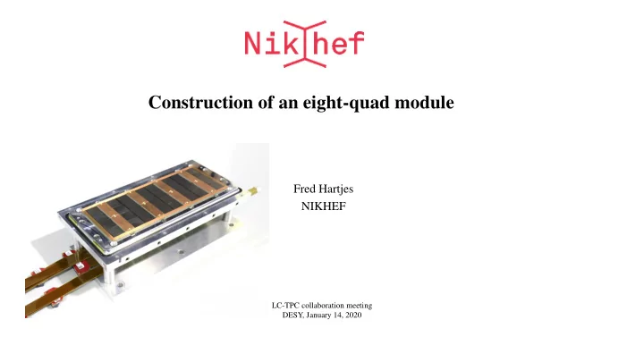
Construction of an eight-quad module
Fred Hartjes NIKHEF
LC-TPC collaboration meeting DESY, January 14, 2020
Construction of an eight-quad module Fred Hartjes NIKHEF LC-TPC - - PowerPoint PPT Presentation
Construction of an eight-quad module Fred Hartjes NIKHEF LC-TPC collaboration meeting DESY, January 14, 2020 GridPix technology Pixel chip with integrated Micromegas => InGrid Grid set at negative voltage (300 600 V) to provide gas
Fred Hartjes NIKHEF
LC-TPC collaboration meeting DESY, January 14, 2020
Fred Hartjes 2 LC-TPC collaboration meeting. DESY. January 14, 2020
Fred Hartjes 3 LC-TPC collaboration meeting. DESY. January 14, 2020
Wafer post-processing at IZM Berlin Aluminium grid (1 µm thick) 35 µm wide holes, 55 µm pitch Supported by SU8 pillars 50 µm high Grid surrounded by SU8 dyke (150 µm wide solid strip) for mechanical and HV stability
Fred Hartjes 4 LC-TPC collaboration meeting. DESY. January 14, 2020
Services under the detector surface of 28.38 x 39.6 mm => may be extended unlimited in the XY plane 12 working QUADs have been produced
Fred Hartjes 5 LC-TPC collaboration meeting. DESY. January 14, 2020
A four TPX3 chip unit, top surface 11.24 cm2 Chips mounted on a base plate (COld CArrier) under high precision
< 20 μm mounting of the chips
Wirebonding to a 6 mm wide PCB in the centre Area for connections IO was minimized
Maximises active area ( 68.9% )
Two electronic boards under the baseplate
LV supply HV board (grid and guard)
Kapton flex for IO signals To maintain a homogenous electric field, the wire bonds are covered by a central guard (omitted on the picture)
TPX3 TPX3 TPX3 TPX3
Fred Hartjes 6 LC-TPC collaboration meeting. DESY. January 14, 2020
Basically the detection surface of a quad TPC can be extended unlimitedly Quads are mounted in holes on a solid cooling plate For practical reasons (handling) it is wise to limit the number of quads to a few tens The detection surface is made gastight, so we make the gas barrier under the COCA
=> the electronics are outside the gas volume
Fred Hartjes 7 LC-TPC collaboration meeting. DESY. January 14, 2020
Solid aluminium support plate with cooling channels Alignment by two L-shaped bars
One having reference notches to align the QUADs One having compression screws to push the QUADs to the alignment bar
4 mm wide guard strips glued onto the L-bars Covering 90 cm2 of which 62 cm2 is active
Fred Hartjes 8 LC-TPC collaboration meeting. DESY. January 14, 2020
Fred Hartjes 9 LC-TPC collaboration meeting. DESY. January 14, 2020
4 cm high drift space Terminated by wires to enable penetration of a laser beam
Fred Hartjes 10 LC-TPC collaboration meeting. DESY. January 14, 2020
Glass plates to enable laser measurements
Fred Hartjes 11 LC-TPC collaboration meeting. DESY. January 14, 2020
The X/Y/Z/j coordinates of all 32 chips have been measured Each chip characterized by 3 points (grid holes)
Fred Hartjes 12 LC-TPC collaboration meeting. DESY. January 14, 2020
Use the alignment microscope with LabVIEW controlled XY stage Presently semi-automatic Method can completely automated using a remotely controlled microscope
Fred Hartjes 13 LC-TPC collaboration meeting. DESY. January 14, 2020
To read out 8 quads simultaneously, the IO flexes have to be connected to two concentrator boards Subsequently both concentrator boards are connected to a single SPIDR board by optical links Programming the firmware of the concentrator boards and SPIDR in progress
Near completion
Fred Hartjes 14 LC-TPC collaboration meeting. DESY. January 14, 2020
Discovered during Bonn testbeam in 2018 Small deformations due to
Dead zone between chips Grounded region between chips
May be corrected by fitted correction function or adding proper guard electrode
Grounded region 1 mm
Fred Hartjes 15 LC-TPC collaboration meeting. DESY. January 14, 2020
Wires being glued on field cage frame
1.1 mm above grids
Field cage frame Field shaping wire
Fred Hartjes 16 LC-TPC collaboration meeting. DESY. January 14, 2020
Wires ~ 1 mm above the grid Optimum voltage deduced from several scan with UV laser beam Potential 55 V more negative than grid voltage
15 V more negative than deduced from drift field effect
Fred Hartjes 17 LC-TPC collaboration meeting. DESY. January 14, 2020
Much larger die => 3.5 x active surface of TimePix3 Same pixel pitch as TPX3 (55 x 55 μm) Electronic peripheries also covered with active pixels 8 x higher RO speed than TPX3
357.7 vs 45 Mhits/cm2
No multiplexing electronics needed
Chips may be daisy chained
Just submitted, first (diced) chips expected end January 2020
24.64 mm (448 pixels) 28.16 mm (512 pixels)
1 superpixel 2x4 pixels 224x64 superpixels
Digital periphery Digital periphery
1 superpixel 2x4 pixels 224x64 superpixels
Analog periphery
Fred Hartjes 18 LC-TPC collaboration meeting. DESY. January 14, 2020
Detector unit based on a single TPX4
Comparable with TPX3 quad Design still at a very preliminary stage
Much less wire bond pads
~ 100 vs 368
Larger wirebond pitch
168 vs 73/146 μm
=> wirebond PCB might be much cheaper Better continuous tracking
~ 45% less boundaries than in TPX3 quad
Active surface for wirebond version > 73% (68.9% for quad) Possibly in future Through Silicon Via (TSV) connections will be realized => active area > 90%
Fred Hartjes 19 LC-TPC collaboration meeting. DESY. January 14, 2020
A module containing 8 quads, covering about 90 cm2 has been realized
62 cm2 of the surface is active
Many performance tests have been done with ionization tracks created by a UV laser to find optimal HV settings Systematic errors on tracks at the edge of the TPX3 chips can be significantly reduced by using guard wires In future a GridPix unit using a TPX4 chip will increase the sensitive area, reduce the length of the boundaries and reduce the costs
Fred Hartjes 20 LC-TPC collaboration meeting. DESY. January 14, 2020
Fred Hartjes 21 LC-TPC collaboration meeting. DESY. January 14, 2020
Liquid cooling by drilled channels, connected by silicon tubing
Most reliable in this stage of prototyping
Fred Hartjes 22 LC-TPC collaboration meeting. DESY. January 14, 2020
XYZ measurement in two steps across the full length and width Base plate very bad flatness
More than 300 um
Corresponds with variations in thickness of the plate
=> underside may be well flat
Some torsion in Y
Two chips tilted
100 and 150 um
Fred Hartjes 23 LC-TPC collaboration meeting. DESY. January 14, 2020
Two chips were tilted (~ 250 µm) Caused by slanting cutting edge of certain chips