
SLIDE 1
COLD Spray POWDER REQUIREMENTS Selection criteria: only the powders - - PowerPoint PPT Presentation
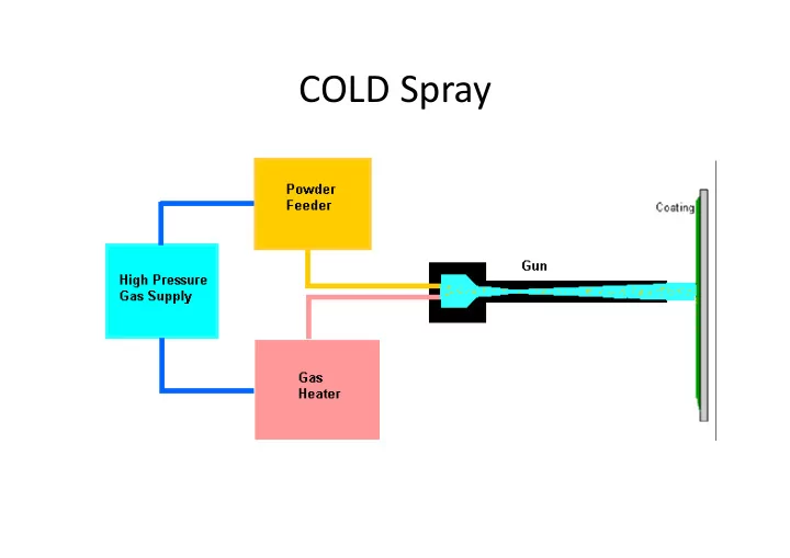
COLD Spray POWDER REQUIREMENTS Selection criteria: only the powders of materials that can deform plastically, can be sprayed by cold spray. Ceramics and polymers cannot be applied by cold spray. Thus Metals and Alloys are the main
POWDER REQUIREMENTS
cold‐spray.
– Face Centred Cubic (F.C.C.): structure metals, such as Al, Cu, Ag, Au, Pt, Ni, and γ‐Fe Having large number of planes and thus can be deformed and are thus best for cold spray – Body Centred Cubic (B.C.C.): structure metals, such as W, Ta, Mo, Nb, V, Cr, α‐Fe and β‐Ti. – Hexagonal Close‐Packed (H.C.P.): structure metals, such as Cd, Zn, Co, Mg and Ti.
deformability.
the ability to spray.
316/304 or the alloy TiAl8V4, are difficult to spray.
successfully processed by this technique.
Cr3C2, have also been obtained in this way .
(15μm) with an optimized initial working gas (nitrogen).
Plasma Giken Kogyo co., ltd
S.No Parameter Value 1 Stagnation jet pressure, MPa (psi) 1‐3 (145‐435) 2 Stagnation jet temperature, °C 0–700 3 Gas flow rate, m3/min ( 1–2 4 Powder feed rate, kg/h 2–8 5 Spray distance, mm 10–50 6 Power consumption, kW (for heating gas) 5‐25 7 Particle size, μm 1–50 8 Operating gases Air, N2, He, and their mixtures Typical range of gas‐jet parameters for cold spray
melting
particles
microstructure
thicker coatings
cooling requirement
preparation
heating required
not be sprayed without using ductile binders
coating
stage, little coating performance/history data
High Temperature resistant Coating that can withstand heat during ironing
The probe (a) before the exposure and (b) after the 5900 h exposure in the biomass co‐fired boiler. On the left side the section with specimens at 550 C and on the right the specimens at 750 C
Optical micrographs of the coatings and the T92 reference material after the exposure at 550 C. (a) T92, (b) NiCr‐F_CJS, (c) IN65_DJ, and (d) NiCr‐C_DJ. EDX analyses of the corrosion scales of T92 (1, 2) are presented below the images [wt.%]
PROCES PARAMETERS OF CGDS AND HVOF Parameter He processing N2 processing Values Values Gun temperature 400 0C 450 0C Gun pressure 20 bars 38 bars Powder flow rate 18 g/min 15 g/min Carrier gas flow rate 3.0 m3/hr 3.0 m3/hr Number of passes 4 6
Sr.no Gas Flow (LPM) Operating pressure kg/cm3 1 Oxygen 350 10 2 LPG 70 7 3 Air 550 6 Sr.no. Parameter Values 1 Carrier gas (N2) 5 LPM 2 Powder feed rate 36 g/min 3 Average particle temperature 1900 0C 4 Average particle velocity 300 m/s 5 Standoff distance 30 cm 6 Deposition efficiency 40%
(HIPOJET-2700)
IIT, BOMBAY MEC, Jodhpur ASB, Industries Ohio (US)
SUBSTRATE AND POWDER USED
Chemistry of powder Powder particle size Method of manufacturing Co32Ni21Cr8Al0.5Y 10-42μm Gas atomized
Mean = 32.20μm Median = 32.63μm Laser Diffraction Grade C Mn Si P S Cr Mo Ni N 316L 0.018 1.30 0.36 0.032 0.003 16.62 2.07 10.12 0.047
IIT, BOMBAY Powder purchased from M/s. Metallizing Equipment Pvt. Ltd. Jodhpur, trade name MEC 9950 AMF
Deposition properties He processing N2 processing HVOF processing Thickness of coating 320-360μm 105-115μm 165-299μm Microstructural features Dense and compact coating Pores and porosity Porosity and visible defect Surfaces roughness Values Ra (µm) 23.41±1.30 16.04±1 8.41±0.55 Porosity level (%) 0.9±0.8 5±0.9 16±0.9 Interface Mechanically bonded Interface between two particles and porosity present Shrinkage
the molten droplets, porosity and visible defect Extent
plastic deformation of powder particles High degree
plastic deformation Lower degree of plastic deformation High degree
plastic deformation and Shrinkage
the molten droplets
PROPERTIES OF HVOF AND CGDS HE AND N2 PROCESSED CoNiCrAlY SPRAYED DEPOSITION.
AS-SPRAYED CROSS-SECTION OF HVOF AND CGDSPRAYED WITH He ANDN2 CARRIER GASES COATINGS
IIT, BOMBAY
Sr.no. He N2 Density (kg/m3) 01785 1.250 Specific Heat ratio 1.660 at (200C) 1.404 at (150C)
EDX COMPOSITION AT CROSS-SECTION OF CGDS AND HVOF COATINGS
IIT, BOMBAY
SUMMARY
Deposition properties CGDS He processing CGDS N2 processing HVOF processing Thickness of coating 320-360μm 105-150μm 165-299μm Microstructural features Dense and compact coating Pores and porosity Porosity and visible defect Surfaces roughness Values Ra (um) 23.41±1.30 16.04±1 8.41±0.55 Porosity level (%) 0.9±0.8 5±0.9 10±0.9 Extent of plastic deformation of powder particles High degree of plastic deformation Interface between two particles and porosity present due to insufficient plastic deformation High degree of plastic deformation and Shrinkage of the molten droplets Hardness 6.60 6.35 5.04
IIT, BOMBAY
KINETICS OF HVOF AND CGDS SPRAYED WITH He AND N2 COATINGS
inversely proportional to the square root of time, is found to be
when diffusion through the scale is the rate determining process
sample in cm2;
the oxidation at 900 0C for 1000 hrs Kp= 1.28x10⁻⁸ g2/cm4s-1; for HVOF and Kp= 0.510x10⁻⁸ g2/cm4s-1 for CGDS He coating Kp= 0.100x10⁻⁸ g2/cm4s-1 for CGDS N2 coating
IIT, BOMBAY
IIT, BOMBAY
exposure times
SURFACE SCALE MORPHOLOGY OF THE HVOF COATING
Fig.EDX analysis of the HVOF coating after the oxidation at 900 0C for different times
EDX analysis of the HVOF coating after the oxidation at 900 0C for different times
IIT, BOMBAY
Fig.EDX analysis of cross-section of the HVOF coating after the oxidation at 900 0C for different times
EDX analysis of cross-section of the HVOF coating after the oxidation at 900 0C for different times
IIT, BOMBAY
Coatings Weight (N) Track diameter (mm) Velocity (m/s) Rpm Bare 316L 5,10,15 40,60,80 0.4 190,127,96 HVOF 5,10,15 40,60,80 0.4 190,127,96 CGDS He 5,10,15 40,60,80 0.4 190,127,96 CGDS with N2 5,10,15 40,60,80 0.4 190,127,96
WEAR AND FRICTION BEHAVIOUR OF CoNiCrAlY POWDER The coating samples were prepared in the form of square pin with a dimension of 10x10x1 mm and fixed into the square pin fixture having dimension 10x10x0.5 mm size
IIT, BOMBAY
SECTION - I WEAR AND FRICTION OF AS-SPRAYED COATINGS AND BARE 316L STAINLESS STEEL
IIT, BOMBAY
SECTION - I WEAR AND FRICTION OF AS-SPRAYED COATINGS AND BARE 316L STAINLESS STEEL
IIT, BOMBAY
Three important properties of lasers:
(108W – compared to 8W of a normal incandescent bulb) &
Active Medium
Solid crystals such as ruby or Nd:YAG liquid dyes, gases like CO2 or Helium/Neon, semiconductors such as GaAs
Excitation Mechanism
Pump energy into the active medium by one or more of three basic methods; optical, electrical or hemical
High Reflectance Mirror
A mirror which reflects essentially 100% of the laser light
Partially Transmissive Mirror
A mirror which reflects less than 100% of the laser light and transmits the remainder.
This is a device to produce a beam of monochromatic light in which all the waves are in phase or are coherent. Components of laser
Coherent Beam Incoherent beam
Continuous Pulse
IIT Bombay, India
1. Gas lasers – CO2 Laser 2. Solid State lasers – Nd-YAG Laser 3. Semi-conductor ( Diode) laser 4. Fiber-lasers (Ytterbium )- (Output power, pulse energy, repetition rate and pulse width)
Commercially Available lasers have power up to 12-20 kW in CW made Diode lasers of power upto 10 kW are available For surface Engineering – solid State lasers/Diode lasers are equally good
IIT Bombay, India
Example of laser Alloying
750 mm/min 625 mm/min 575 mm/min 500 mm/min
Oxidation behaviour at 800oC Corrosion behaviour in 1N H2SO4 Consequence of Laser Alloying on the Oxidation and Corrosion Behaviour Of Steel
Development of Super‐austenitic SS using Ni‐Cr‐Mo Alloying
Sample designation Scan speed (mm/min) Laser power (watts) Spot Size (mm2) Melt Depth ( µm) Effect of laser Scan Speed LSA 1 500 3000 0.5x6.0 405 LSA 2 750 3000 0.5x6.0 383 LSA3 1000 3000 0.5x6.0 361 LSA4 1250 3000 0.5x6.0 432 Effect of laser Power LSA 5 750 1000 0.5x6.0 364 LSA 6 750 2000 0.5x6.0 431 LSA 2 750 3000 0.5x6.0 383 LSA 7 750 4000 0.5x6.0 425 Effect of Spot Size LSA 2 750 3000 0.5x6.0 383 LSA 9 750 3000 0.75x6.0 649 LSA 8 750 3000 1.0x6.0 683
Corrosion Behaviour of laser alloyed 304 SS – better than commercially Available SM) 254
Showing Better Pitting Behaviour Plasma Coating of Ni % Mo.
Cross section after laser Treatment
Surface Morphology
Without Cladding After Cladding with Ni-25Cr-alloy
Laser Parameters
Sample No. Scan Speed (mm/min) 1 400 100Ni 2 500 3 600 4 1000 100WC 5 1200 6 800 7 800 35WC 8 1000 9 600
Laser Glazed Coatings
Laser Type :::: Nd:YAG Laser Power :::: 2000 W Shielding gas :::: Ar at 30 lt /min Nozzle Substrate :::: 260mm Distance
Laser Alloying Process and Coated Samples
Characterization of Coatings Surface Characteristics Sample Ra (μm) 100%NiCrBSi 9.011 15%WC/Co 85%NiCrBSiFe 5.558 35%WC/Co 65%NiCrBSiFe 8.467 60%WC/Co 40%NiCrBSiFe 9.387 100%WC/Co 7.644 100%NiCrBSiFe Coating 15%WC/Co- 85%NiCrBSiFe 35%WC/Co 65%NiCrBSiFe Coating 60%WC/Co 40%NiCrBSiFe Coating 100%WC/Co Coating
IIT Bombay, India
MECHANICAL PROPERTIES OBTAINED
Sample Name Yield Strength (MPa) UTS (MPa) Elongat ion (%) A1 (along the layers) 550 840
A2 (Heat treated) 602 1051
B1(Perpe ndicular to layers) 415 688
B2 (Heat treated) 306 370
0.5 1 1.5 2 2.5 3 200 400 600 800 1000 1200
Weight gain in gms/cm2 Time in hrs
conventional Inconel 718 Laser formed alloy
0.0001 0.0002 0.0003 0.0004 0.0005 0.0006 0.0007 0.0008 0.0009 100 200 300 400 500 600 700
Weight change in gms/cm2 Time in Hrs Sulphidation Behaviour
Conventional alloy 718 Laserformed Inconel 718
Ingomar Kelbassa1, Ernst Wolfgang Kreutz1, Patrick Albus1, Leping Zhu2 FIL, Aachen
UTS) and YS of laser cladded Inconel 718 T = 20 °C and at T = 650 °C Green – NO HT Red HT 730oC 4H