Circuits in the frequency domain ENGR 40M lecture notes August 2, - - PDF document

circuits in the frequency domain
SMART_READER_LITE
LIVE PREVIEW

Circuits in the frequency domain ENGR 40M lecture notes August 2, - - PDF document

Circuits in the frequency domain ENGR 40M lecture notes August 2, 2017 Chuan-Zheng Lee, Stanford University Our study of capacitors and inductors has so far been in the time domain. In some contexts, like transient response, this works fine,


slide-1
SLIDE 1

Circuits in the frequency domain

ENGR 40M lecture notes — August 2, 2017 Chuan-Zheng Lee, Stanford University Our study of capacitors and inductors has so far been in the time domain. In some contexts, like transient response, this works fine, but in many others, the time domain can be both cumbersome and uninsightful. As we hinted last lecture, the frequency domain can give us a more powerful view of how circuits operate.
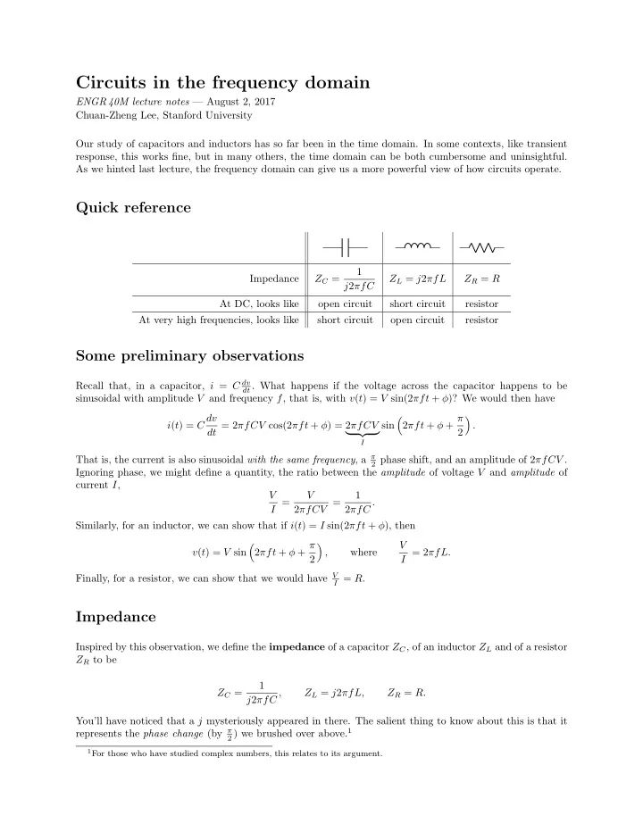
Quick reference

Impedance ZC = 1 j2πfC ZL = j2πfL ZR = R At DC, looks like

  • pen circuit

short circuit resistor At very high frequencies, looks like short circuit

  • pen circuit

resistor

Some preliminary observations

Recall that, in a capacitor, i = C dv

dt . What happens if the voltage across the capacitor happens to be

sinusoidal with amplitude V and frequency f, that is, with v(t) = V sin(2πft + φ)? We would then have i(t) = C dv dt = 2πfCV cos(2πft + φ) = 2πfCV

I

sin

  • 2πft + φ + π

2

  • .

That is, the current is also sinusoidal with the same frequency, a π

2 phase shift, and an amplitude of 2πfCV .

Ignoring phase, we might define a quantity, the ratio between the amplitude of voltage V and amplitude of current I, V I = V 2πfCV = 1 2πfC . Similarly, for an inductor, we can show that if i(t) = I sin(2πft + φ), then v(t) = V sin

  • 2πft + φ + π

2

  • ,

where V I = 2πfL. Finally, for a resistor, we can show that we would have V

I = R.

Impedance

Inspired by this observation, we define the impedance of a capacitor ZC, of an inductor ZL and of a resistor ZR to be ZC = 1 j2πfC , ZL = j2πfL, ZR = R. You’ll have noticed that a j mysteriously appeared in there. The salient thing to know about this is that it represents the phase change (by π

2 ) we brushed over above.1

1For those who have studied complex numbers, this relates to its argument.

slide-2
SLIDE 2

More precisely, j is defined to be the number such that j2 = −1, and is known as the imaginary unit. You might have seen this in mathematics, where it took the symbol i. You probably thought that such imaginary ideas would never have real applications. As it happens, electrical engineers have very elegant uses for it.2 In this class, we will write j in our expressions for completion, but when performing precise calculations, we’ll just pretend it’s not there. Naturally, this will lead to answers that are not quite right.3 For our purposes, this doesn’t make much difference. (Fair warning: in some other applications, it makes a huge difference.)

Extreme cases

The special case f = 0 indicates how the circuit responds to the DC component of a Fourier series. We say that this is the circuit’s behavior at DC. In this case, ZC = ∞, so a capacitor looks like an open circuit; and ZL = 0, so an inductor looks like a short circuit. The opposite extreme is when f → ∞. This isn’t physically realizable, but it provides an intuition for how circuits will behave at very high frequencies. In this case, ZC → 0, so a capacitor looks like a short circuit, and ZL → ∞, so an inductor looks like an open circuit. f = 0 (DC) f = ∞ ZC ↓ decreasing ZC ↑ increasing

  • pen

short ZL ↑ increasing ZL ↓ decreasing short

  • pen

ZR constant ZR constant still R still R Note that our DC characterizations match the steady state from last week. This isn’t a coincidence; in fact, the “steady state” we discussed is more accurately called the DC steady state (in contrast to AC). Resistors don’t exhibit frequency-dependent behavior. They just stay with ZR = R, always. For this reason, we often don’t bother replacing R with ZR in our algebraic work.

Circuits in the frequency domain

Armed with our new tool, we can proceed to analyze circuits with sinusoidal sources, with no derivatives in sight—see Examples 1 and 2. In fact, because impedance represents a ratio between voltage and current, in the frequency domain, we can use impedance to analyze circuits as if they were a resistor network. The

  • nly difference is that these impedances can be frequency-dependent.

But there’s still more. Because the frequency domain is just a means of expressing a signal as a sum of sinusoids, we can use a superposition-based argument to see that circuits just operate on each frequency component of an input signal independently. That is, any voltage or current in the circuit can be found by (1) decomposing the input into its frequency components, (2) applying our impedance-based analysis to each frequency component, and then (3) adding the results together. In many circuits, the output amplitude Vout is just a (frequency-dependent) multiple of the input amplitude

  • Vin. In such cases, we often talk of the gain of a circuit, Vout

Vin . Where the gain is a function of frequency, we

sometimes call it the transfer function.

2We don’t have the mathematical tools to derive our expressions for impedance more rigorously. The “proper” way to do it

involves the Fourier transform (an extension of the Fourier series) and complex exponentials (ejx), and requires us to introduce a notion of “negative frequency”.

3To get the precise answer, you would need to find the magnitude of a complex number. You’re welcome to do this if you

like; we’ll accept either answer in homework and exams.

2

slide-3
SLIDE 3

Examples

Example 1. Consider the circuit below, where vin(t) is a sinusoid with frequency f and amplitude Vin. vin(t) R C

+

− vout(t) (a) Find an expression for Vout, the amplitude of vout(t), in terms of Vin and f. (b) If vin(t) is a 1 kHz sinusoid with amplitude 300 mV, and R = 10 kΩ and C = 100 nF, what is the amplitude of vout(t)? Example 2. Consider the circuit below, where vin(t) is a sinusoid with frequency f and amplitude Vin. vin(t) R L

+

− vout(t) (a) Find an expression for Vout, the amplitude of vout(t), in terms of Vin and f. (b) If vin(t) is a 700 Hz sinusoid with amplitude 1 V, and R = 100 Ω and L = 400 ➭H, what is the amplitude

  • f vout(t)?

Example 3. Consider the circuit from Example 1 (again). vin(t) 10 kΩ 100 nF

+

− vout(t) (a) Find the gain Vout

Vin of the circuit, as a function of frequency.

(b) What is the gain at (i) DC, and (ii) very high frequencies? Interpret this by describing what you would expect to see at vout(t). (c) The time-domain and frequency-domain representations of an input vin(t) is shown below. Find the frequency-domain representation of the output vout(t). 3

slide-4
SLIDE 4
  • 0.05

0.05 0.1 0.15 0.2 −1 1 2 t vin(t) Time-domain representation 10 1000 0.5 1 1.5 f (Hz) Vin Frequency-domain representation Example 4. Consider the circuit from Example 2 (again). vin(t) 100 Ω 400 ➭H

+

− vout(t) (a) Find the gain Vout

Vin of the circuit, as a function of frequency.

(b) What is the gain at (i) DC, and (ii) very high frequencies? Interpret this by describing what you would expect to see at vout(t). (c) The frequency-domain representation of an input vin(t) is shown below. Find the frequency-domain representation of the output vout(t), then (roughly) sketch its time-domain representation. 1 kHz 1 MHz 1 2 f Vin Frequency-domain representation of vin(t) 4