
SLIDE 1
Chapter 6 Storage & Other I/O
2
Chapter 6 Storage & Other I/O 5 components of a Computer - - PDF document
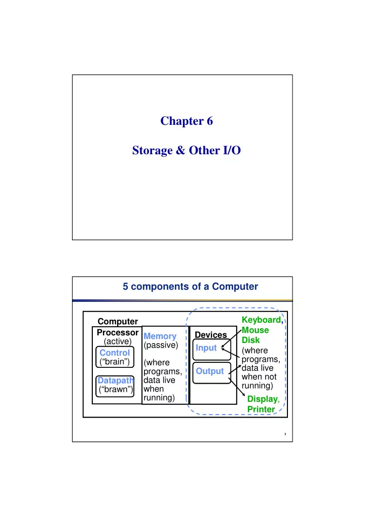
Chapter 6 Storage & Other I/O 5 components of a Computer Keyboard, Computer Mouse Processor Devices Memory Disk (active) (passive) Input (where Control programs, (brain) (where data live programs, Output when not
2
3
4
5
Main memory I/O controller I/O controller I/O controller Disk Graphics
Network Memory–I/O bus Processor Cache Interrupts Disk
6
7
(from mouse to display: million-to-1)
8
9
10
10 bytes header 512 Bytes data 12 bytes ECC
11
Platter Track Platters Sectors Tracks
12
surfaces (usually)
rotate under head, then read or write
Bytes); error correction code per sector to find and correct errors
13
14
15
Controller Overhead
is from head
density), size of request
16
— seek: position head over the proper track (8 to 20 ms. avg.) — rotational latency: wait for desired sector (.5 / RPM) — transfer: grab the data (one or more sectors) 2 to 15 MB/sec
17
18
19
20
21
22
23
24
25
26
27
28
29
30
Firewire USB 2.0 PCI Express Serial ATA Serial Attached SCSI Intended use External External Internal Internal External Devices per channel 63 127 1 1 4 Data width 4 2 2/lane 4 4 Peak bandwidth 50MB/s or 100MB/s 0.2MB/s, 1.5MB/s, or 60MB/s 250MB/s/lane 1, 2, 4, 8, 16, 32 300MB/s 300MB/s Hot pluggable Yes Yes Depends Yes Yes Max length 4.5m 5m 0.5m 1m 8m Standard IEEE 1394 USB Implementers Forum PCI-SIG SATA-IO INCITS TC T10
31
32
33
34
35
36
37
38
39