
SLIDE 1
1
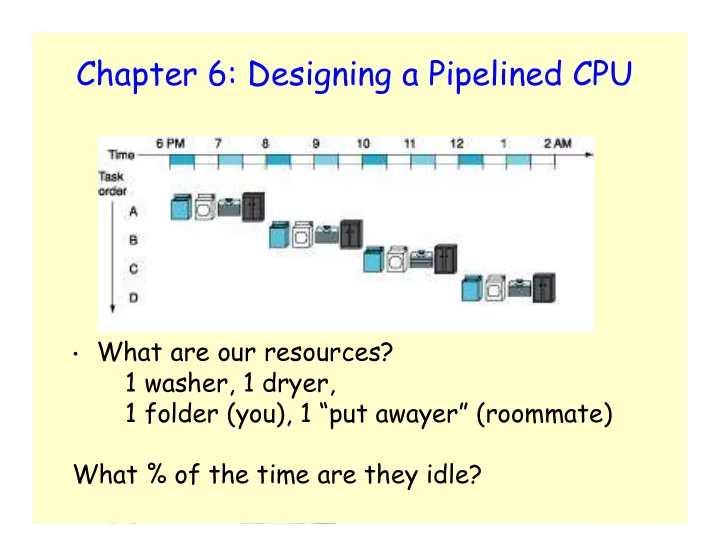
Chapter 6: Designing a Pipelined CPU
- What are our resources?
Chapter 6: Designing a Pipelined CPU What are our resources? 1 - - PowerPoint PPT Presentation
Chapter 6: Designing a Pipelined CPU What are our resources? 1 washer, 1 dryer, 1 folder (you), 1 put awayer (roommate) What % of the time are they idle? 1 2 Chapter 6: Designing a Pipelined CPU Chapter 6: Designing a Pipelined CPU
1
2
3
4
5
6
7
8
9
CC1 CC2 CC3 CC4 CC5 CC6 CC7 CC8 CC9
lw lw lw lw lw
steady state IF ID EX MEM WB IM Reg ALU DM Reg IF ID EX MEM WB IM Reg ALU DM Reg IF ID EX MEM WB IM Reg ALU DM Reg IF ID EX MEM WB IM Reg ALU DM Reg IF ID EX MEM WB IM Reg ALU DM Reg
10
Cycle 1 Cycle 2 Cycle 3 Cycle 4 Cycle 5 Cycle 6 Cycle 7 Cycle 8 IF Dec EX Mem WB Load IF Dec EX Mem WB Load IF Dec EX Mem WB Load IF Dec EX Mem WB Load Cycle 1 Cycle 2 Cycle 3 Cycle 4 Cycle 5 IF Dec EX Mem WB Load
IF Dec EX Mem WB Load IF Dec EX Mem WB Cycle 6 Cycle 7 Cycle 8 Cycle 9Cycle 10 IF Dec EX Mem WB Cycle 1 Cycle 2
Load Load
11
12
13
CC1 CC2 CC3 CC4 CC5 CC6
IF Dec EX Mem WB IF Dec EX WB
14
CC1 CC2 CC3 CC4 CC5 CC6
IF Dec EX Mem WB IF Dec EX WB
Mem
15
IM Reg ALU DM Reg IF ID EX MEM WB
16
Instruction Fetch Instruction Decode/ Register Fetch Execute/ Address Calculation Memory Access Write Back
Instruction memory Address 4 32
Add Add result
Shift left 2 IF/ID EX/MEM MEM/WB M u x 1
Add
PC Write data M u x 1 Registers Read data 1 Read data 2 Read register 1 Read register 2 16 Sign extend Write register Write data Read data 1
ALU result
M u x
ALU Zero
ID/EX Data memory Address