Router Architectures CPU CPU Memory Memory packets NFE NFE - - PowerPoint PPT Presentation

router architectures
SMART_READER_LITE
LIVE PREVIEW

Router Architectures CPU CPU Memory Memory packets NFE NFE - - PowerPoint PPT Presentation

Router Architectures CPU CPU Memory Memory packets NFE NFE Processor Processor Line Card Line Card Line Card CPU CPU CPU Line Card Line Card #1 #1 #4 Memory Memory Memory #4 #4 CPU CPU CPU CPU Line Card Line Card Line


slide-1
SLIDE 1

Router Architectures

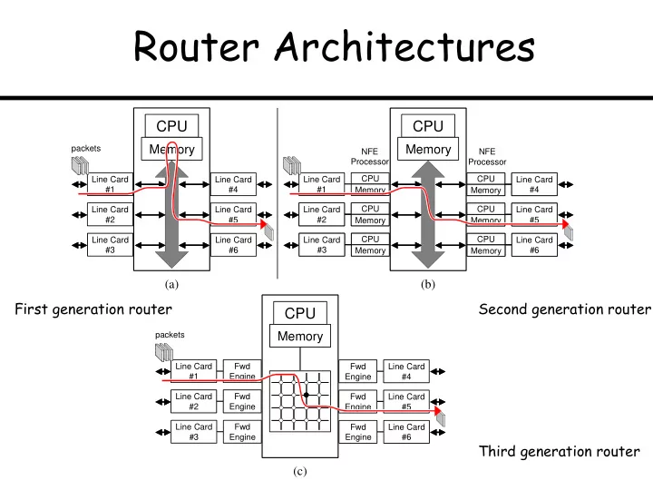
CPU Line Card #1 Memory CPU Line Card #2 Memory CPU Line Card #2 Memory CPU Line Card #3 Memory CPU Line Card #3 Memory CPU Line Card #4 Memory CPU Line Card #4 Memory CPU Line Card #5 Memory CPU Line Card #5 Memory CPU Line Card #6 Memory CPU Line Card #6 Memory Line Card #1

CPU

Line Card #2 Line Card #3 Line Card #4 Line Card #5 Line Card #6

Memory

CPU

Memory

NFE Processor NFE Processor

(a) (b)

Fwd Engine Fwd Engine Line Card #2 Fwd Engine Line Card #1 Line Card #3 Fwd Engine Line Card #4 Fwd Engine Line Card #5 Fwd Engine Line Card #6

CPU

Memory (c)

packets packets

First generation router Second generation router Third generation router

slide-2
SLIDE 2

Switching via Memory / via Bus

CPU Memory Line card Line card System bus Link layer Network layer

packets

Input port Output port Forwarding & Routing processor CPU Memory Line card Line card System bus Link layer Network layer

packets

Input port Output port Forwarding & Routing processor NFE processor NFE processor CPU Memory Line card Line card System bus Link layer Network layer

packets

Input port Output port Routing processor NFE processor NFE processor CPU Memory Line card Line card System bus Link layer Network layer

packets

Input port Output port Routing processor

First generation router Second generation router

slide-3
SLIDE 3

Crossbar Switch Fabric

Input Output

N x N switching elements allows N simultaneous packets switched (in the best case when all packets going to different outputs)

slide-4
SLIDE 4

Goal: Reduce # Switching Elements

  • System bus (in 1st and 2nd generation arch’s)

allows only one packet switched at a time

  • Crossbar allows up to N packets switched at

a time

  • Something in the middle? (+cheaper!)
slide-5
SLIDE 5

Banyan Switch Fabric

1 1 Input port tag Output port tag 1 Packet with tag 1 1 1 Input port tag Output port tag 1 Packet with tag 1 00 01 10 11 00 01 10 11 00 01 10 11 00 01 10 11 Input port tag Output port tag

000 001 010 011 100 101 110 111 000 001 010 011 100 101 110 111 100

Packet with tag 100

001

Packet with tag 001 Input port tag Output port tag

(a) (b) (c)

8x8 Banyan has only 12 switching elements (while 8x8 crossbar requires 64) But, much greater likelihood of collisions…

slide-6
SLIDE 6

Reducing Collisions

  • (Show slide with a collision example)
  • Collisions can be reduced if packets are
  • rdered on input ports by their output port

number

  • The router cannot choose the ordering of

arriving packets, but we can insert a sorting hardware between the input network ports and the switching fabric …

slide-7
SLIDE 7

Batcher Network

5 3 3 5 Input numbers Output numbers Low High

Comparator

5 3 3 5 Input numbers Output numbers Low High

Comparator

7 5 3 4 L H 3 5 4 7 L H 4 5 L H L H L H 5 3 7 4 7 5 3 4 L H 3 5 4 7 L H 4 5 L H L H L H 5 3 7 4

9 5 6 4 3 2 1 7

Input list

1 2 3 4 5 6 7 9

Output list

5 4 9 6 2 1 3 7 4 1 5 2 6 3 9 7 4 2 5 3 6 7 4 3 5 7

(a) (b) (c)

slide-8
SLIDE 8

Batcher-Banyan Network

Batcher sort network Trap network Shuffle exchange network Banyan network

slide-9
SLIDE 9

Why Batcher-Banyan Network

This figure is meant to illustrate why a concentrator is needed, because otherwise the gap in the input sequence will cause collision in the Banyan, but the example does not work for a 4x4 network -- need an 8x8 network example!!!!

1 3 1 2 1 2 2 1 2 1 1

Batcher sorter Trap network

2 1

Banyan network

Packets with tags 1, 0, 0, 2 2 Empty input