
SLIDE 1
1
IC220 Set #11: Storage and I/O
2
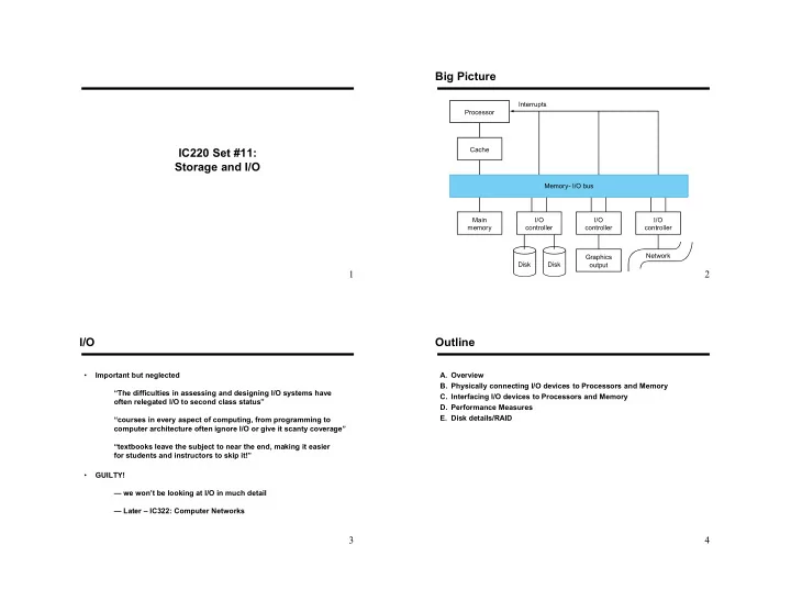
Big Picture
Disk Disk Processor Cache Memory- I/O bus Main memory I/O controller I/O controller I/O controller Graphics
- utput
Network Interrupts
3
I/O
- Important but neglected
“The difficulties in assessing and designing I/O systems have
- ften relegated I/O to second class status”
“courses in every aspect of computing, from programming to computer architecture often ignore I/O or give it scanty coverage” “textbooks leave the subject to near the end, making it easier for students and instructors to skip it!”
- GUILTY!
— we won’t be looking at I/O in much detail — Later – IC322: Computer Networks
4
Outline
- A. Overview
- B. Physically connecting I/O devices to Processors and Memory
- C. Interfacing I/O devices to Processors and Memory
- D. Performance Measures
- E. Disk details/RAID