SLIDE 1
Biaxial minerals
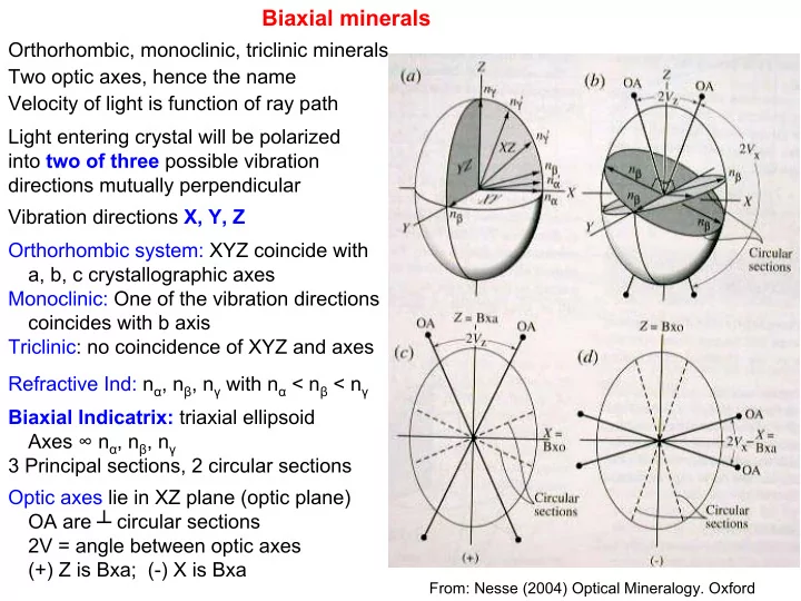
Orthorhombic, monoclinic, triclinic minerals Two optic axes, hence the name Velocity of light is function of ray path Light entering crystal will be polarized into two of three possible vibration directions mutually perpendicular Vibration directions X, Y, Z Orthorhombic system: XYZ coincide with a, b, c crystallographic axes Monoclinic: One of the vibration directions coincides with b axis Triclinic: no coincidence of XYZ and axes Refractive Ind: nα, nβ, nγ with nα < nβ < nγ Biaxial Indicatrix: triaxial ellipsoid Axes ∞ nα, nβ, nγ 3 Principal sections, 2 circular sections Optic axes lie in XZ plane (optic plane) OA are ┴ circular sections 2V = angle between optic axes (+) Z is Bxa; (-) X is Bxa
From: Nesse (2004) Optical Mineralogy. Oxford
SLIDE 2
Biaxial minerals (cont.) Light passing through crystal normal to XZ plane has max difference in RI (nγ – nα), i.e., max birefringence, and highest interference colors. Light passing through crystal parallel to optic axis behaves as if crystal is isotropic (grain remains dark as stage is rotated). All other orientations show intermediate effects (a) Orthorhombic: X, Y, Z coincide with a, b, c (b) Monoclinic: Y =b. X and Z lie in a-c plane (010) (c) Triclinic: no coincidence except by chance
From: Nesse (2004) Optical Mineralogy. Oxford
SLIDE 3
Biaxial minerals (Interference figures)
Interference figures observed depend on orientation of crystal. By far the two most useful figures are obtained when an optic axis or Bxa is parallel to the scope axis (┴ stage). Int. fig. used to determine (a) uniaxial or biaxial, (b) optic sign and (c) 2V angle. Centered Bxa figure (acute bisectrix is vertical) Bxa + Z (+), Bxa = X (-)
45° position 90° position
M = melatope: point where the two optic axes emerge A figure like this would correspond to a 2V or ~40° Centered Bxa figures are frequently difficult to locate in biaxial minerals
From: Nesse (2004) Optical Mineralogy. Oxford
SLIDE 4
Biaxial minerals (Interference figures)
90º position ~20º position 45º position
These figures show the orientation of the vibration directions in a biaxial mineral with a 2V of ~30º, viewed with conoscopic illumination. Note that the image appears dark when the vibration directions are oriented parallel to the privileged directions of the polarizer and analyzer. In the 45º position the isogyres form hyperbolae. M = melatope; OP = optic plane; ON = optic normal
From: Nesse (2004) Optical Mineralogy. Oxford
SLIDE 5 Biaxial minerals (Interference figures) Formation of isochromes in Bxa figure. Isochromes form along bands of equal
- retardation. Note:conoscopic incident light
Orientation of vibration directions in a Bxa figure projected on to the upper surface of the mineral
From: Nesse (2004) Optical Mineralogy. Oxford
SLIDE 6 Biaxial minerals (Interference figures) 2V angle: 2V angle is a useful diagnostic feature so it is useful to attempt to estimate it. In a centered Bxa figure, the closer the melatopes and the stronger curvature of the isogyres the lower the 2V angle as shown. At a 2V of ~45°, the isogyres just leave the field of view when the high power objective has a numerical aperture of 0.65. To obtain an interference figure:
- 1. Focus on a sample with high power objective
- 2. Flip in the auxiliary condenser lens to provide
conoscopic illumination: light now impinges
- n the sample at an angle that increases
- utwards.
- 3. Cross the polarizers
- 4. Insert the Bertrand lens
From: Nesse (2004) Optical Mineralogy. Oxford
SLIDE 7
Biaxial minerals (Interference figures) Centered Optic axis figure (optic axis is vertical)
90°position 45°position
This centered optic axis figure show the orientation of the vibration directions and the resultant isogyres. As the stage is rotated cw the isogyres are rotated ccw. Low 2V (~20°) 2V ~ 60°
From: Nesse (2004) Optical Mineralogy. Oxford
SLIDE 8 Biaxial minerals (Interference figures) Centered Optic axis figure (optic axis is vertical) This figure is intended to provide a guide to estimating the 2V angle in a centered optic axis figure. Not the straight isogyre for 2V = 90° In my view, centered optic axis figures are the most useful because grains that give such figures are the easiest to locate in a thin section. For any particular mineral, choose a grain that show the lowest interference colors, meaning that the grain is cut almost ┴ to
- ne of the optic axes. The
interference figure will look like
- ne of those in the diagram
From: Nesse (2004) Optical Mineralogy. Oxford
SLIDE 9 Biaxial minerals (Interference figures) Determination of optic sign using a Bxa figure
- 1. Locate a grain that gives
a Bxa figure (can be off- center and still be useful)
- 2. Rotate to 45º position
- 3. Insert gypsum (530 nm)
compensating plate and note interference color change immediately adjacent to melatopes
- 4. (+) Yellow on convex side
- f isogyres (blue on
concave means Z is Bxa; (-) blue on convex side and yellow on concave means X is Bxa. Y is always the optic normal
From: Nesse (2004) Optical Mineralogy. Oxford
SLIDE 10 Biaxial minerals (Interference figures) Determination of optic sign using a
- ptic axis figure
- 1. Locate a grain that gives an optic
axix figure (can be off-center and still be useful)
- 2. Rotate to 45º position
- 3. Insert gypsum (530 nm)
compensating plate and note interference color change immediately adjacent to melatopes
- 4. (+) Yellow on convex side of
isogyres (blue on concave means Z is Bxa; (-) blue on convex side and yellow on concave means X is
- Bxa. Y is always the optic normal
From: Nesse (2004) Optical Mineralogy. Oxford
SLIDE 11
Biaxial minerals (cont.)
Extinction angles: Extinction in a biaxial mineral may be parallel (exctinction angle = 0 relative to a prominent crystal face or cleavage direction), symmetrical (relative to prominent cleavage directions), or oblique (extinction is at an angle to a prominent crystal face or cleavage direction) cleavage Vibration directions Parallel extinction Inclined extinction Symmetrical extinction Pleochroism: Biaxial minerals may show pleochroism with different transmission colors for the three different vibration directions. Recall: pleochroism can only be determined in plane polarized light. The pleochroic formula is the color of a mineral when each of the vibration directions is parallel to the lower polarizer (E-W), e.g., the pleochroic formula might be: X = blue, Y = light green, Z = dark green. To determine pleochroic formula, you need to know the optical orientation of the grain.