At the least, compute one Tap in a 2. Separate AGU from DALU for - - PDF document

at the least compute one tap in a
SMART_READER_LITE
LIVE PREVIEW

At the least, compute one Tap in a 2. Separate AGU from DALU for - - PDF document

SCOPES 2003 Outline Tailoring Software Pipelining For 1. Low-power DSP 16000 and ZOLB Effective Exploitation Of Zero 2. Compiler Mission Overhead Loop Buffer 3. Conventional Approach 4. Alternatative approach 5. Intermediate


slide-1
SLIDE 1

1 SCOPES 2003 Tailoring Software Pipelining For Effective Exploitation Of Zero Overhead Loop Buffer Gang-Ryung Uh

CS Department Boise State University
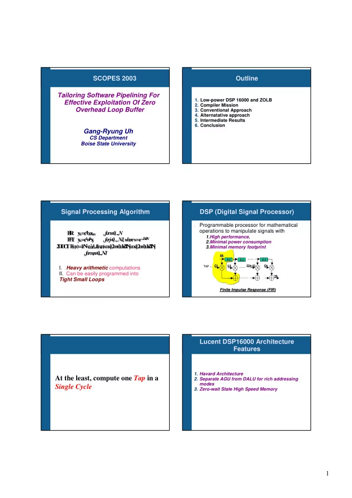
Outline

  • 1. Low-power DSP 16000 and ZOLB
  • 2. Compiler Mission
  • 3. Conventional Approach
  • 4. Alternatative approach
  • 5. Intermediate Results
  • 6. Conclusion

Signal Processing Algorithm

F I R : y

k

= ¢ ² b

n

x

k

  • n

, f

  • r

n = , ..,N F F T : y

k

= ¢² w

j k

x

j , f

  • r

j = , .., N

  • 1

, w h e r e w = e-2

i¥ð /N 2

D

  • D

C T : F ( u ,v ) = 1 / N

2 ¢² m

¢ ²n

f

( m ,n ) c

  • s[

( 2 m + 1 ) u ¥ð / 2 N ] c

  • s[

( 2 n + 1 ) u ¥ð / 2 N ] , f

  • r

m ,n = ,..,N

  • 1

I. Heavy arithmetic computations

  • II. Can be easily programmed into

Tight Small Loops

DSP (Digital Signal Processor)

Programmable processor for mathematical

  • perations to manipulate signals with
  • Finite Impulse Response (FIR)

Finite Impulse Response (FIR)

  • 1.High performance,

2.Minimal power consumption 3.Minimal memory footprint

At the least, compute one Tap in a Single Cycle

Lucent DSP16000 Architecture Features

  • 1. Havard Architecture
  • 2. Separate AGU from DALU for rich addressing

modes

  • 3. Zero-wait State High Speed Memory
slide-2
SLIDE 2

2 Lucent DSP16000 Architecture Features (cont)

  • 4. Compiler (Programmer) Controlled On-Core

Instruction Cache – ZOLB (Zero Overhead Loop Buffer) to support high performace high performace with minimal minimal power dissipation power dissipation

Instruction buffer Instruction 1 Instruction 2 ... Instruction 31 cloop k cstate ... zolbpc n .... d

  • c

lo

  • p

{ in str u c tio n 1 .... .... r ed

  • k

in str u c tio n n .... } ...

Lucent DSP16000 Instruction Set Design

In order to achieve performance & higher code density

Permissible order of operations is very limited The register usage is restricted to only a few different

registers A0 = A0 + P0 P0 = Xh*Yh P1 = Xl * Yl Y = *R0++ X = *PT0++

16 bit word instruction

Compiler Mission!

Where are the compound/complex instructions?

A2=0 j=a4 do 50 { /* inst 1 */ xh = *(r0 + j) /* inst 2 */ yh = *r3++ /* inst 3 */ r4 = j /* inst 4 */ p0 = xh*yh p1 = xl*yl /* inst 5 */ a2 = a2+p0 /* inst 6 */ j = r4+1 } A0 = A0 + P0 P0 = Xh*Yh P1 = Xl * Yl Y = *R0++ X = *PT0++

  • // EDN Benchmarks

fir(const short array1[ ], const short coeff[], short output[])

{ int i,j,sum; for(i=0;i < N-ORDER;i++){ sum=0; for(j=0; j < ORDER; j++){ sum += array1[i+j]*coeff[j]; }

  • utput[i]=sum>>15;

} }

Experience with Iterative Modulo Scheduling Techniques

fir(const short array1[ ], const short coeff[], short output[]) { int i,j,sum; for(i=0;i < N-ORDER;i++){ sum=0; for(j=0; j < ORDER; j++){ sum += array1[i+j]*coeff[j]; }

  • utput[i]=sum>>15;

} }

a2=0 j=a4 do 50 { /* inst 1 */ xh = *(r0 + j) /* inst 2 */ yh = *r3++ /* inst 3 */ r4 = j /* inst 4 */ p0 = xh*yh p1 = xl*yl /* inst 5 */ a2 = a2+p0 /* inst 6 */ j = r4+1 }

EDN Benchmark: FIR Filter

Step 1: Resource Inition Interval

do 50 { /* inst 1 */ xh = *(r0 + j) /* inst 2 */ yh = *r3++ /* inst 3 */ r4 = j /* inst 4 */ p0 = xh*yh p1 = xl*yl /* inst 5 */ a2 = a2+p0 /* inst 6 */ j = r4+1 }

Inst 1 Inst 2 Inst 3 Inst 4 Inst 5 Inst 6 ResII: Resource Initiation Interval ?

MII = MAX(RecII, ResII)

ResII : Smallest Loop Initiation Interval

to meet the system resource requirement

2

Inst 1 Inst 2 Inst 3 Inst 4 Inst 5 Inst 6

True Dependence Output Dependence do 50 { /* inst 1 */ xh = *(r0 + j) /* inst 2 */ yh = *r3++ /* inst 3 */ r4 = j /* inst 4 */ p0 = xh*yh p1 = xl*yl /* inst 5 */ a2 = a2+p0 /* inst 6 */ j = r4+1 }

(0,1) (0,1) (0,1) (1,1)

Anti Dependence

(1,0) (0,1)

MII = MAX(RecII, ResII)

RecII : Smallest Integer Loop Initiation

Interval to meet all the deadlines imposed by data dependence circuits.

(1,1) (1,0) (1,0)

Step 2: Recurrence Initiation Interval

slide-3
SLIDE 3

3

Inst 1 Inst 2 Inst 3 Inst 4 Inst 5 Inst 6 Start End

S t a r t I n s t

  • 1

I n s t

  • 2

I n s t

  • 3

I n s t

  • 4

I n s t

  • 5

I n s t

  • 6

E n d S t a r t X (0 ,0 ) ( , ) (0 ,0 ) ( ,0 ) ( , ) ( ,0 ) ( ,0 ) I n s t

  • 1

X X X X ( ,1 ) X X ( ,0 ) I n s t

  • 2

X X X X ( ,1 ) X X ( ,0 ) I n s t

  • 3

X X X X X X ( ,1 ) ( ,0 ) I n s t

  • 4

X (1 ,0 ) ( ( 1 ,0 ) X X ( , 1 ) X ( ,0 ) I n s t

  • 5

X X X X ( 1 ,0 ) X X ( ,0 ) I n s t

  • 6

X (1 ,1 ) X (1 ,1 ) X X X ( ,0 )

Adjacency Matrix

Step 2: RecII (cont)

(0,0)

S t a r t I n s t

  • 1

I n s t

  • 2

I n s t

  • 3

I n s t

  • 4

I n s t

  • 5

I n s t

  • 6

E n d S t a r t X ( , ) ( , ) ( ,0 ) ( ,0 ) ( ,0 ) ( , ) ( , ) I n s t

  • 1

X X X X ( ,1 ) X X ( , ) I n s t

  • 2

X X X X ( ,1 ) X X ( , ) I n s t

  • 3

X X X X X X ( , 1 ) ( , ) I n s t

  • 4

X ( 1 , ) ( ( 1 ,0 ) X X ( ,1 ) X ( , ) I n s t

  • 5

X X X X ( 1 ,0 ) X X ( , ) I n s t

  • 6

X ( 1 , 1 ) X ( 1 ,1 ) X X X ( , )

Adjacency Matrix

Step 2: Compute MinDIST Matrix

S t a r t I n s t

  • 1

I n s t

  • 2

I n s t

  • 3

I n s t

  • 4

I n s t

  • 5

I n s t

  • 6

E n d S t a r t

X 1 2 1 2

I n s t

  • 1

X

  • 1
  • 1

X 1 2 X 2

I n s t

  • 2

X

  • 1
  • 1

X 1 2 X 2

I n s t

  • 3

X

  • 1

1 2 1 2

I n s t

  • 4

X

  • 2
  • 2

X

  • 1

1 X 1

I n s t

  • 5

X

  • 4
  • 4

X

  • 2
  • 1

X

I n s t

  • 6

X

  • 1
  • 2
  • 1

1 1

E n d

X X X X X X X X

Floyd Algorithm: MinDist[i,i] 0

with II (Initiation Interval) 2

Step 3: Slack Scheduling by computing Estart and Lstart

S t a r t I n s t

  • 1

I n s t

  • 2

I n s t

  • 3

I n s t

  • 4

I n s t

  • 5

I n s t

  • 6

E n d S t a r t

X 1 2 1 2

I n s t

  • 1

X

  • 1

X 1 2 X 2

I n s t

  • 2

X

  • 1

X 1 2 X 2

I n s t

  • 3

X

  • 1

1 2 1 2

I n s t

  • 4

X

  • 2
  • 2

X 1 X 1

I n s t

  • 5

X

  • 4
  • 4

X

  • 2

X

I n s t

  • 6

X

  • 1
  • 2
  • 1

1 1

E n d

X X X X X X X X

Floyd Algorithm: MinDist[i,i] 0

with II (Initiation Interval) 2

O peration Slack I ssue T im e E start L start I nst-1 1 I nst-2 1 1 I nst-3 1 I nst-4 1 1 1 I nst-5 1 1 I nst-6 1 1 1

Legal Partial Schedule based on Estart and Lstart

Why Modulo Scheduling is not suitable?

Operation Slack I ssue T ime Estart L start I nst-1 1 I nst-2 1 1 I nst-3 1 I nst-4 1 1 1 I nst-5 1 1 I nst-6 1 1 1

Legal Partial Schedule based on SLACK // inst-1 && inst-3

xh=*(r0+j) r4=j

// inst-2 && inst-4 && inst-5 && inst-6

yh=*r3++ p0=xh*yh p1=xl*yl a2=a2+p0 j=r4+1

No Legal Encoding

Why Modulo Scheduling is not suitable?

Due to limited encoding space Due to limited encoding space, DSP16000 compound instructions that account for {Inst {Inst-

  • i,

i, Inst Inst-

  • j, Inst

j, Inst-

  • k}

k},but there is NO legal encoding to capture any subset of {Inst {Inst-

  • i,Inst

i,Inst-

  • j,Inst

j,Inst-

  • k}

k}

How to Overcome?

Software pipelining optimization must be

sensitive to Instruction Selection

This requires that the Instruction selection

performs the following tasks in a demand driven manner

proactively perform Register Renaming proactively introduce additional micro-

  • perations on the fly
slide-4
SLIDE 4

4 New Compiler Strategy

?T

a s k 1 : P a r ti ti

  • n

a g i v e n l

  • p

b

  • d

y i n t

  • n

i n s t r u c t i

  • n

g r

  • u

p s , G

1

, G

2

, .., G

n

, s u c h t h a t i n s t r u c t i

  • n

s i n G

i

c a n b e p

  • t

e n t i a l l y s c h e d u l e d i n G

k

, w h e r e k = ( i + 1 ) , ( i + 2 ) , ..., n .

?T

a s k 2 : R e s tr u c tu r e t h e l

  • p

s u c h t h a t i t s b

  • d

y c

  • n

s i s t s

  • f

n i n s t r u c t i

  • n

g r

  • u

p s , w h e r e e a c h g r

  • u

p i s s e l e c t e d f r

  • m

a d i f f e r e n t l

  • p

i t e r a t i

  • n

.

?T

a s k 3 : P e r f

  • r

m I n s tr u c ti

  • n

S e l e c ti

  • n

a m

  • n

g n g r

  • u

p s i n t h e r e s t r u c t u r e d l

  • p

b

  • d

y s u c h t h a t s e l e c t e d i n s t r u c t i

  • n

s c a n b e c

  • m

b i n e d i n t

  • f

e w e r i n s t r u c t i

  • n

s . I f n e c e s s a r y , p e r f

  • r

m r e g i s t e r r e n a m i n g

  • r

/ a n d p r

  • a

c t i v e l y i n t r

  • d

u c e e x t r a i n s t r u c t i

  • n

( s ) t

  • r

e f

  • r

m a p

  • t

e n t i a l s e t

  • f

p a r a l l e l o p e r a t i

  • n

s to a l e g a l D S P 1 6 e n c

  • d

i n g .

Potentially Pipelineable

Instructions Ii and Ij are potentially pipelineable potentially pipelineable only when the following two conditions can be met.

1.There exists a compound/complex instruction template that can hold (may be more) both effects Ii and Ij in parallel. This implies that Ii and Ij can be potentially combined into a single complex instruction. 2.The Distance from Ii in the instruction Group Gk to Ij can meet the Minimum Distance requirements ( (MinDist[i,j] MinDist[i,j]). )..

Another FIR Filter from a Customer

I n st r u c t i

  • n D

S P C

  • d

e F r a g m e n t d

  • 9

2 { I 1 y = * r + + x = * p t + + I 2 p = x h * y h p 1 = x l * y l I 3 a = * r 2 I 4 a = a + p 1 I 5 * r 2 + + = a I 6 a = * r 2 I 7 a = a + p I 8 * r 2 + + = a }

S t a r t I n s t

  • 1

I n s t

  • 2

I n s t

  • 3

I n s t

  • 4

I n s t

  • 5

I n s t

  • 6

I n s t

  • 7

I n s t

  • 8

E n d S t a r t

( X ,X ) ( ,0 ) ( ,0 ) ( ,0 ) ( ,0 ) ( ,0 ) ( ,0 ) ( ,0 ) ( ,0 ) ( ,0 )

I n s t

  • 1

( X ,X ) (

X , X ) ( , 1 ) ( X ,X ) ( X , X ) ( X ,X ) ( X ,X ) ( , ) ( X , X ) (

,0 )

I n s t

  • 2

( X ,X ) (

1 , ) ( X , X ) ( X ,X ) ( , 1 ) ( X ,X ) ( X ,X ) ( , 1 ) ( X , X ) (

,0 )

I n s t

  • 3

( X ,X ) (

X , X ) ( X , X ) ( X ,X ) ( , 1 ) ( ,1 ) ( ,1 ) ( , 1 ) ( , 1 ) (

,0 )

I n s t

  • 4

( X ,X ) (

X , X ) ( 1 , ) ( 1 ,1 ) ( X , X ) ( ,1 ) ( ,1 ) ( , 1 ) ( , 1 ) (

,0 )

I n s t

  • 5

( X ,X ) (

X , X ) ( X , X ) ( 1 ,1 ) ( 1 , ) ( X ,X ) ( ,1 ) ( , ) ( , 1 ) (

,0 )

I n s t

  • 6

( X ,X ) (

X , X ) ( X , X ) ( 1 ,1 ) ( 1 , 1 ) ( 1 ,1 ) ( X ,X ) ( , 1 ) ( , 1 ) (

,0 )

I n s t

  • 7

( X ,X ) (

X , X ) ( 1 , ) ( 1 ,1 ) ( 1 , 1 ) ( 1 ,1 ) ( 1 ,1 ) ( X , X ) ( , 1 ) (

,0 )

I n s t

  • 8

( X ,X ) (

X , X ) ( X , X ) ( 1 ,1 ) ( 1 , ) ( 1 ,1 ) ( 1 ,1 ) ( 1 , ) ( X , X ) (

,0 )

E n d

( X ,X ) ( X ,X ) ( X ,X ) ( X ,X ) ( X ,X ) ( X ,X ) ( X ,X ) ( X ,X ) ( X ,X ) ( X ,X )

Another FIR Filter from a Customer

I n st r u c t i

  • n D

S P C

  • d

e F r a g m e n t d

  • 9

2 { I 1 y = * r + + x = * p t + + I 2 p = x h * y h p 1 = x l * y l I 3 a = * r 2 I 4 a = a + p 1 I 5 * r 2 + + = a I 6 a = * r 2 I 7 a = a + p I 8 * r 2 + + = a }

S t a r t I n s t

  • 1

I n s t

  • 2

I n s t

  • 3

I n s t

  • 4

I n s t

  • 5

I n s t

  • 6

I n s t

  • 7

I n s t

  • 8

E n d S t a r t

X 1 1 2 3 4 5 6 6

I n s t

  • 1

X

  • 5

1 1 2 3 4 5 6 6

I n s t

  • 2

X

  • 6
  • 2

1 2 3 4 5 5

I n s t

  • 3

X

  • 8
  • 2

1 2 3 4 5 5

I n s t

  • 4

X

  • 9
  • 3
  • 1

1 3 3 4 4

I n s t

  • 5

X

  • 1
  • 4
  • 2
  • 1

1 2 3 3

I n s t

  • 6

X

  • 1

1

  • 5
  • 3
  • 2
  • 1

1 2

2

I n s t

  • 7

X

  • 1

2

  • 6
  • 4
  • 3
  • 2
  • 1

1

1

I n s t

  • 8

X

  • 1

3

  • 7
  • 5
  • 4
  • 3
  • 2
  • 1

E n d

X X X X X X X X X X

MinII = 6 MinDist[ ][ ] Matrix

Step 1: Partition

I n st r u c t io n D S P C

  • d

e F r a g m e n t d

  • 9

2 { I 1 y = * r + + x = * p t + + I 2 p = x h * y h p 1 = x l* y l I 3 a = * r 2 I 4 a = a + p 1 I 5 * r 2 + + = a I 6 a = * r 2 I 7 a = a + p I 8 * r 2 + + = a }

G1 = {I1} G2 = {I2} G2 = {I2 , I3} G2 = {I2 ,I3 ,I4} G2 = {I2 ,I3 ,I4 ,I5} G2 = {I2 ,I3 ,I4 ,I5 ,I6} G3 = {I7} G3 = {I7 ,I8} a0=a0+p0 p0=xh*yh p1=xl*yl y=*r0++ x=*pt0++ a0=a0+p0 p0=xh*yh p1=xl*yl y=*r0++ x=*pt0++

/* initialization */ void partition( ) { create a new group G1; add an instruction I1 to G1; i = 2; j = 1; FOR each instruction Ii in the loop DO { FOR each instruction Ik in Gj { IF (Ik and Ii are potentially pipelinable) { j = j+1; create a new group Gj ; Tag Gj and Gj–1 with complex instruction templates; break; } } add an instruction Ii to Gj; i = i + 1; } }

a0=a0+p0 p0=xh*yh p1=xl*yl y=*r0++ x=*pt0++

Step 2: Project a Maximally Pipelined Loop

1st ITERATION G1 G2 Gn

. . .

2nd ITERATION G1 Gn-1 Gn

. . .

(N-1)th ITERATION G1 G2 Gn-1

. .

Gn Nth ITERATION G1 Gn-1

. .

Gn ? ? ? Software pipelined loop body

slide-5
SLIDE 5

5

Step 2: Project a Perfectly Pipelined Loop

1

st I

T ER A T I O N G 1 G 2 G n

. . .

2

nd IT

ERA T I O N G 1 G n-1 G n

. . .

(N-1)th I T E RA T IO N G 1 G 2 G n-1

. .

G n N

th I

T ER A T I O N G 1 G n-1

. .

G n ? ? ? Software pipelined loop body Gro u p G 1 Y = *R0++ X = *PT0++ Gro u p G 3 A0=A0+P0 *R2++=A0 Gro u p G 2 P0=Xh*Yh P1=Xl*Yl A0 = *R2 A0 = A0 + P1 *R2++ = A0 A0 = *R2 2 n d ITE R ATION 3 rd ITE R ATION Gro up G 1 Y = *R0++ X = *PT0++ Gro u p G 1 Y = *R0++ X = *PT0++ Gro u p G 3 A0 =A0 +P0 *R2++=A0 Gro u p G 3 A0=A0+P0 *R2++=A0 Gro u p G 2 P0 =Xh *Yh P1=Xl*Yl A0 = *R2 A0 = A0 + P1 *R2++ = A0 A0 = *R2 Gro u p G 2 P0=Xh *Yh P1=Xl*Yl A0 = *R2 A0 = A0 + P1 *R2++ = A0 A0 = *R2

Instruction Selection Algorithm

/* MAIN */

DO { change = FALSE;; FOR each instruction group GI DO { IF = first instruction in group GI; IF (IF == NULL) CONTINUE; IF (change == FALSE) change = Combine_Insts(IF,GI+1); ELSE (void) Combine_Insts(IF,GI+1); /* Advance to the next instruction group */ i = i + 1; } /* end of FOR */ } WHILE (change == TRUE) /* COMBINE INSTRUCTIONS */ BOOLEAN Combine_Insts(IM,GN) { BOOLEAN Success = FALSE; IF (GN == NULL) /* GN is empty */ return FALSE; F= first instruction in GN; FOR each instruction IF in GN DO { IF (there exists F1/F1E instruction template that accounts for effects IFM ) { IF (Scheduling IM at the same time slot for IF does violate a deadline imposed by some instruction in GN) /* It is not legal schedule */ continue; IF (IFM satisfies the register encoding restrictions) { replace IF with IFM; remove IM from GN-1; Success = TRUE; break; } ELSE IF (there exist available register(s) that can make ILM satisfy the register encoding restrictions) { perform register renaming; tag the IFM with the F1/F1E instruction template; remove IM from GN-1; Success = TRUE; break; } } ELSE F = F + 1; } /* END FOR */ Merge GN-1 and GN into one instruction group; RETURN FALSE; } /* END COMBINE_INSTS */

Discover Complex Instruction by Overlapping G2 and G1

a0=a0+p0 p0=xh*yh p1=xl*yl y=*r0++ x=*pt0++

COMBINE_INSTS

Group G2

P0 = Xh*Yh P1 = Xl*Y Y = *R0++ X = *PT0++ P0 = Xh*Yh P1 = Xl*Y Y = *R0++ X = *PT0++ A0 = *R2 A0 = A0 + P1 *R2++ = A0 A0 = *R2

a0=a0+p0 p0=xh*yh p1=xl*yl y=*r0++ x=*pt0++ a0=a0+p0 p0=xh*yh p1=xl*yl y=*r0++ x=*pt0++ Group G1

Y = *R0++ X = *PT0++ Y = *R0++ X = *PT0++

Group G2

P0=Xh*Yh P1=Xl*Yl P0=Xh*Yh P1=Xl*Yl A0 = *R2 A0 = A0 + P1 *R2++ = A0 A0 = *R2

Group G3

A0=A0+P0 *R2++=A0

Discover Complex Instruction by Overlapping G3 and G2

a0=a0+p0 p0=xh*yh p1=xl*yl y=*r0++ x=*pt0++ Group G2

P0 = Xh*Yh P1 = Xl*Y Y = *R0++ X = *PT0++ P0 = Xh*Yh P1 = Xl*Y Y = *R0++ X = *PT0++ A0 = *R2 A0 = A0 + P1 *R2++ = A0 A0 = *R2

Group G3

A0=A0+P0 A0=A0+P0 *R2++=A0

COMBINE_INSTS

Group G2

// combined with Group // combined with Group G

G1

1 A0 = *R2 A0 = A0 + P1 *R2++ = A0 A0 = *R2

Group G3

A0=A0+P0 P0 = Xh*Yh P1 = Xl*Y Y = *R0++ X = *PT0++ A0=A0+P0 P0 = Xh*Yh P1 = Xl*Y Y = *R0++ X = *PT0++ *R2++=A0

Merge Instruction Groups G3 and G2

Group G3

A0 = A0+P0 P0=Xh*Yh P1=Xl*Yl Y=*R0++ X=*PT0++ *R2++ = A0 A0 = *R2 A0 = A0 + P1 *R2++ = A0 A0 = *R2

Group G3

A0=A0+P0 P0 = Xh*Yh P1 = Xl*Y Y = *R0++ X = *PT0++ A0=A0+P0 P0 = Xh*Yh P1 = Xl*Y Y = *R0++ X = *PT0++ *R2++=A0

Group G2

// combined with Group // combined with Group G

G1

1 A0 = *R2 A0 = A0 + P1 *R2++ = A0 A0 = *R2

MERGE_GROUPS(G3,G2)

Kernel

Restructured Loop

1st loop iteration 2nd loop iteration 91st loop iteration 92nd loop iteration Group G3

A0 = A0+P0 P0=Xh*Yh P1=Xl*Yl Y=*R0++ X=*PT0++ *R2++ = A0 A0 = *R2 A0 = A0 + P1 *R2++ = A0 A0 = *R2 Group G1

Y = *R0++ X = *PT0++

Group G2

P0=Xh*Yh P1=Xl*Yl A0 = *R2 A0 = A0 + P1 *R2++ = A0 A0 = *R2

Group G1

Y = *R0++ X = *PT0++

1st loop iteration

Group G3

A0=A0+P0 *R2++=A0

Group G2

P0=Xh*Yh P1=Xl*Yl A0 = *R2 A0 = A0 + P1 *R2++ = A0 A0 = *R2

Group G3

A0=A0+P0 *R2++=A0

91st loop iteration

slide-6
SLIDE 6

6 Results

B e n c h m a r k T e st P r

  • g

r a m s

P ro g ra m D e sc rip tio n a d d 8 A d d tw

  • 8
  • b

it im a g e s c

  • n

v

  • lu

tio n C

  • n

v

  • lu

tio n c

  • d

e c

  • p

y 8 C

  • p

y

  • n

e 8

  • b

it im a g e to a n

  • th

e r f f t 1 2 8 p

  • in

t c

  • m

p le x F F T f ir F in ite I m p u lse R e sp

  • n

se f ilte r f ir _ n

  • _

r e d _ ld F I R f ilte r w ith r e d u n d a n t lo a d e lim in a tio n f ir e F I R E e n c

  • d

e r iir I I R f ilte r in g in v e r se 8 I n v e r t a n 8

  • b

it im a g e jp e g d c t J P E G D isc r e te C

  • sin

e T r a n sf

  • r

m a tio n sc a le 8 S c a le a n 8

  • b

it im a g e su m a b sd if f s S u m

  • f

a b s d if f s o f tw

  • im

a g e s v e c _ m p y S im p le v e c to r m u ltip ly

Execution Time

add 8 con vo- lu- cop y8 fft fir fir_ no_ red fire iir in- ver se8 jpe gdc t sca le8 su ma bs vec _m py

  • 0.75
  • 0.7
  • 0.65
  • 0.6
  • 0.55
  • 0.5
  • 0.45
  • 0.4
  • 0.35
  • 0.3
  • 0.25
  • 0.2
  • 0.15
  • 0.1
  • 0.05

Table 2. Impact on Execution Time

Using a ZOLB Instruction Selection together with Using a ZOLB

Rate Reduction in Machine Cycles

Code Size

add 8 con vo- lu- cop y8 fft fir fir_ no_ red fire iir in- ver se8 jpe gdc t scal e8 su ma bs vec _m py

  • 0.25

0.25 0.5 0.75 1 1.25 1.5 1.75 2 2.25 2.5 2.75 3

Table 3. Impact on Code Size

Loop Unrolling Using ZOLB Instruction Selection to- gether with Using a ZOLB

Rate Increase in Code Size

Conclusion

  • 1. New Compiler Strategy that automatically exploits

compound instructions

  • 2. As a result of this work, the Zero Overhead Loop

Buffer on Lucent DSP16000 can be further exploited SCOPES 2003 Outline Signal Processing Algorithm DSP (Digital Signal Processor) At the least, compute one Tap in a Single Cycle Lucent DSP16000 Lucent DSP16000 Example of Using ZOLB on the DSP16000 Instruction Set Design for Low-power

Embedded Processors

Instruction Set Design for Low-power

Embedded Processors

Where are the compound/complex