Assignments Checkpoint 7 High Dynamic Range Imagery / Due Monday - - PDF document

assignments
SMART_READER_LITE
LIVE PREVIEW

Assignments Checkpoint 7 High Dynamic Range Imagery / Due Monday - - PDF document

Assignments Checkpoint 7 High Dynamic Range Imagery / Due Monday Image Based Graphics Raytracer Code Due Wednesday RenderMan Due February 16th Projects Logistics Project feedback Final Report Approx


slide-1
SLIDE 1

1

High Dynamic Range Imagery / Image Based Graphics

Assignments

  • Checkpoint 7

– Due Monday

  • Raytracer Code

– Due Wednesday

  • RenderMan

– Due February 16th

Projects

  • Project feedback
  • Approx 18 projects
  • Listing of projects now on Web
  • Presentation schedule

– Just Feb 16th and Feb 21st – Feb 14th – project preparation day

  • ALL PROJECTS HAVE BEEN SCHEDULED

Logistics

  • Final Report

– Introduction – Approach Taken – Implementation Details – Results – Appendix/Code
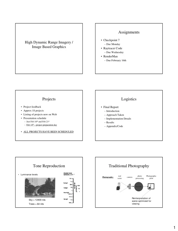
Tone Reproduction

  • Luminance levels

Sky = 12400 nits Trees = 64 nits

Traditional Photography

camera

processing

photo processing real scene Photographic print Photography:

Reinterpretation of scene optimized for viewing

slide-2
SLIDE 2

2

Digital Photography

camera

processing

Processing performed by camera real scene Digital image Photography:

Reinterpretation of scene optimized for viewing (24 bit RGB)

Image Synthesis in CG

camera synthetic image camera model

processing

photo processing tone reproduction real scene 3D models Photographic print Photography: Computer Graphics:

Reinterpretation of scene

  • ptimized for viewing

(24 bit RGB) Scene luminance

High Dynamic Range (HDR) Imaging

  • high dynamic range imaging is a set of

techniques that allow a far greater dynamic range

  • f exposures than normal digital imaging

techniques.

  • The intention is to accurately represent the wide

range of intensity levels found in real scenes, ranging from direct sunlight to the deepest shadows.

Wikipedia

HDR in Computer Graphics

[Ward 2001]

HDR in Computer Graphics

[Debevec 2001]

HDR Issues

  • Creation of HDR Images
  • Storage
  • Display
  • Usage
slide-3
SLIDE 3

3

Creating HDR images

  • CG Simulation

– Ray tracing – Radiosity

  • Multiple Camera Exposure

Creating HDR Images

time shutter eff. flare scene from luminance

4 2

) cos 4 ( ) ( t I n L x

f

η θ π τ + = ′

Lens transmittance

Aperture / f-stop

Creating HDR Images

[Debevec 1997]

30 sec 15 sec 8 sec 4 sec 2 sec 1 sec ½ sec ¼ sec 1/8 sec 1/15 sec 1/30 sec 1/60 sec 1/100 sec 1/250 sec 1/500 sec 1/1000 sec

Storing HDR Images

  • File formats developed for research

– Log Encoding (Pixar – TIFF) – RGBE (Radiance) – Log luv (SGI, TIFF) – OpenEXR (ILM) – scRGB (Microsoft / HP)

  • http://www.anyhere.com/gward/hdrenc/

High Dynamic Range Images

  • OpenEXR

– Introduced by Industrial Light and Magic (ILM) for their computer imagery work. – First used in

  • Harry Potter and Sorcerer’s Stone
  • Men in Black II
  • Gangs of New York
  • Signs

– Now used on all ILM film effects projects.

High Dynamic Range Images

  • OpenEXR

– Can encode

  • 9 log units of dynamic range with no loss of precision

– Also supports

  • Compression (lossless & lossy)
  • Ability to store “metadata”
  • Arbitrary number of image channels
  • Compatable with Graphics hardware and Realtime Shader

systems.

– File format and tookit source is open source. – http://www.openexr.org

slide-4
SLIDE 4

4

HDR Displays

  • Prototypes in development

– 50,000:1 DR – 300:1 – typical device

  • Note: Tone Reproduction

still required for hard copy

  • utput

[Seetzen, et al 2004]

[Debevec 1998]

HDR in Computer Graphics

http:/ / www.debevec.org/ RNL/

HDR in Computer Graphics HDR in Computer Graphics HDR in Computer Graphics

[Debevec 1998]

HDR in Computer Graphics

Let’s see this again

slide-5
SLIDE 5

5 HDR in Computer Graphics

Radiance Maps

  • Environment mapping using physical

lighting values.

– Encodes actual light quantities

slide-6
SLIDE 6

6

http://www.debevec.org/FiatLux/ Combined image-based modeling, rendering and lighting to place monoliths and spheres into a photorealistic reconstruction of St. Peter’s Basilica

Fiat Lux

break

Blurring the line between geometry and light

  • Our perception of object geometry is based on the

light emitted from them

  • Light stored as a 4D entity (lumigraph/light field)

– Describes flow of light in all directions as precalculated and stored radiance – Ray tracing utilizes these stored values

  • Independently discovered and published in 1996:

– Lumigraph – Gortler, et al. – Light Field Rendering – Levoy and Hanrahan

The Lumigraph

  • a next generation photograph that allows

you to see an image from any angle you can think of. This is a digital equivalent to a hologram.

The lumigraph

  • All light from an object

can be represented as if it were coming from a cube

  • Each point on the cube

has a number of rays coming from it

slide-7
SLIDE 7

7

The lumigraph

  • Each wall of the cube is

actually two parallel planes

  • Rays are parameterized

by where they intersect these planes

  • Any point in the 4D

Lumigraph is identified by it’s coordinates (s,t,u,v)

The lumigraph The lumigraph

Hanrahan, Levoy 1996

Computer Graphics and Computer Vision

processing processing

Computer graphics Computer vision

Image Based Modeling

Image Based Modeling

slide-8
SLIDE 8

8 Image Based Modeling Image Based Modeling Image Based Modeling

  • Introduced THREE new techniques!
  • Photogrammetric modeling using model-based stereo

algorithm

– User represents scene as a collection of 3D primitives, e.g.,blocks. – Computer solves for sizes and positions of blocks according to user- supplied edge correspondence.

  • Rendered using view dependent texture mapping

– Issues include view dependent lighting, shadows, specular reflection – May need to warp photo details to fit geometry

Image Based Modeling That’s all folks

  • Next week:

– Student Presentations – Recall: No lecture on Monday!

  • One last bit of business

– Course evaluations.