ANALYTICA CAL STUDY O ON P POST-BU BUCK CKLI LING RESIDUAL S L - - PDF document

analytica cal study o on p post bu buck ckli ling
SMART_READER_LITE
LIVE PREVIEW

ANALYTICA CAL STUDY O ON P POST-BU BUCK CKLI LING RESIDUAL S L - - PDF document

18 TH INTERNATIONAL CONFERENCE ON COMPOSITE MATERIALS ANALYTICA CAL STUDY O ON P POST-BU BUCK CKLI LING RESIDUAL S L STRENGTH O H OF F STEEL EL F FRA RAME H. Park 1 , J. Kim 1 , Daniel Y. 1 , J. Choi 2 * 1 Graduate, Department of


slide-1
SLIDE 1

18TH INTERNATIONAL CONFERENCE ON COMPOSITE MATERIALS

1 Introduction Accidental collapse of a structure has an impact on columns or column groups by means of falling

  • bjects. Column members on the lower part are

damaged due to shocking caused by collapse at the upper part. For this case, researchers have studied how to prevent progressive collapse although columns on the lower part are damaged. 1)2) There is a great need to assess actual behavior of structural damage due to accidental loads; to develop a model for accident prevention performance assessment reliable for enhancing safety of a structure. Therefore, in this study, we analyzed the non-linear finite element of a one-story 4-span steel frame to assess energy absorption for accidental loss of

  • columns. And also we did limit analysis to compare

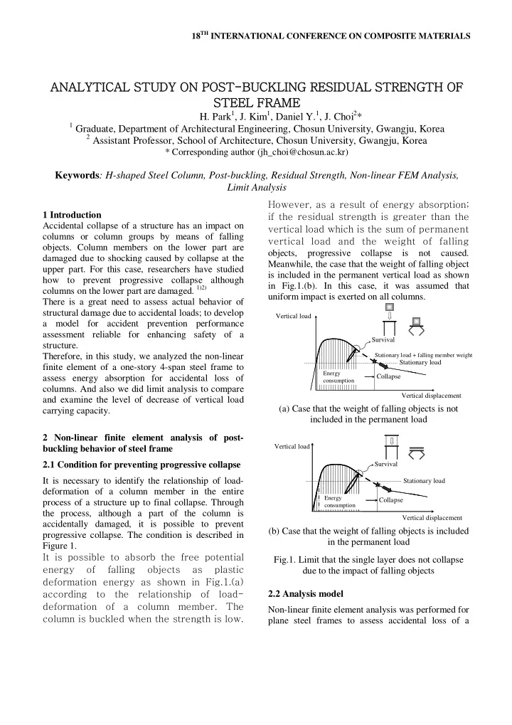
and examine the level of decrease of vertical load carrying capacity. 2 Non-linear finite element analysis of post- buckling behavior of steel frame 2.1 Condition for preventing progressive collapse It is necessary to identify the relationship of load- deformation of a column member in the entire process of a structure up to final collapse. Through the process, although a part of the column is accidentally damaged, it is possible to prevent progressive collapse. The condition is described in Figure 1. It is possible to absorb the free potential energy

  • f

falling

  • bjects

as plastic deformation energy as shown in Fig.1.(a) according to the relationship of load- deformation of a column member. The column is buckled when the strength is low. However, as a result of energy absorption; if the residual strength is greater than the vertical load which is the sum of permanent vertical load and the weight of falling

  • bjects,

progressive collapse is not caused. Meanwhile, the case that the weight of falling object is included in the permanent vertical load as shown in Fig.1.(b). In this case, it was assumed that uniform impact is exerted on all columns. (a) Case that the weight of falling objects is not included in the permanent load (b) Case that the weight of falling objects is included in the permanent load Fig.1. Limit that the single layer does not collapse due to the impact of falling objects 2.2 Analysis model Non-linear finite element analysis was performed for plane steel frames to assess accidental loss of a

ANALYTICA CAL STUDY O ON P POST-BU BUCK CKLI LING RESIDUAL S L STRENGTH O H OF F STEEL EL F FRA RAME

  • H. Park1, J. Kim1, Daniel Y.1, J. Choi2*

1 Graduate, Department of Architectural Engineering, Chosun University, Gwangju, Korea 2 Assistant Professor, School of Architecture, Chosun University, Gwangju, Korea

* Corresponding author (jh_choi@chosun.ac.kr)

Keywords: H-shaped Steel Column, Post-buckling, Residual Strength, Non-linear FEM Analysis, Limit Analysis

Vertical load Vertical displacement Collapse Survival

Stationary load + falling member weight

Stationary load

Energy consumption

Vertical load Vertical displacement Collapse Survival Stationary load

Energy consumption

slide-2
SLIDE 2
  • column. The analysis model is shown in Fig.2 to

model the 1-story 4-span plane frame in which 5 columns of H-100x100x6x8 were arranged with an assumed rigid body on top, as a cell element. The constraint condition of the upper rigid body was modeled to be the following 2 types. The first condition was to model the case of constraining rigid beam rotation by allowing displacement only in the vertical direction and constraining displacement and all rotations in the other directions. The second condition was to model the case of free rotation of rigid beams by allowing only the rotation which enables displacement and column buckling in the vertical direction and constraining displacement and rotation in the other directions. Assuming sharp increase of loads in collapse, linear incremental loading was applied at 100 mm/sec so that axial loads are given to the upper rigid beam in the vertical direction for applying forced displacement. Fig.2. Analysis model of 1-story 4-span plane frame The material of columns was modeled with SS400 (structural steel), and the upper and lower rigid bodies were modeled with rigid material steel. Properties of each material are shown in Table 1.

Column (SS400) Upper and lower rigid body

Young’s modulus (GPa)

205 205

Poisson’s ratio

0.29 0.3

Density(kg/mm3)

7.845X10⁻⁶ 7.7X10⁻⁶

Yield stress(GPa)

0.31

  • Table.1. Properties of material for the analysis

models

Type Ⅰ Ⅱ Ⅲ Ⅳ Ⅴ Ⅵ Ⅶ Ⅷ Member loss

④ ⑤ ③ + ④ ③ + ⑤ ④ + ⑤ ② + ④

Table.2. Column loss No. for each type Table 2 shows the type of analysis models with accidental loss of each column. 2.3 Result of analysis 2.3.1 Buckling deformation As shown in Fig 3, buckling occurred in the weak axis although both ends are fixed. Local buckling

  • ccurred around both ends in addition to sharp local

buckling in the central part of the columns. It is considered that the great slenderness ratio of the columns contributed to plastic hinge and buckling as described below. (a) Global buckling of the columns (b) Buckling in the center of the columns Fig.3. Buckling deformation of the column 2.3.2 Constrained rotation of rigid body beam

  • Fig. 4 shows the result of analysis of each column

loss for the plane steel frame, provided that rotation

  • f rigid body beams is constrained.

Corner Corner Middle Middle Center

slide-3
SLIDE 3

3 ANALYTICAL STUDY ON POST-BUCKLING RESIDUAL STRENGTH OF PLANE STEEL FRAME

변위 (mm) P/P0

0.2 0.4 0.6 0.8 1 10 20 30 40 50 60 70 80 90 100

TYPE 1 TYPE 2 TYPE 3 TYPE 4 TYPE 5 TYPE 6 TYPE 7 TYPE 8

Fig.4. Relationship of load-displacement, provided that beam rotation was constrained

  • Figs. 5 and 6 show energy absorption in each

position of member loss under post-buckling 30% for each type and vertical displacement under the position of post-buckling strength 30% for each position of member loss. Fig.5. Energy absorption for each position of member loss (post-buckling 30%) Displacement changes in the vertical direction were examined depending on column loss while the post- buckling strength is lowered to 30%. Deformation approximately 80-90% occurred in the vertical direction when one column member was lost as compared to the case that the original 5 columns were not damaged. Deformation of approximately 75- 80% occurred in the vertical direction when two column members were lost. Loss of column members lowered the load transfer capacity to support vertical loads while lowering the deformation capacity. Accordingly, energy absorption capacity sharply decreased on the overall structure. Fig.6. Vertical displacement at the position of post- buckling strength 30% for each position of member loss

Decrease in residual strength on the loss

  • f column member

Deformation ability decreases on the loss of column member No loss of column member 1 loss of column member 2 loss of column member

Fig.7. Decrease in energy absorption depending on the loss of column member 2.3.3 Case of free rotation of rigid body beams

  • Figs. 8, 9 and 10 show the analysis result of column

loss in the 1-story 4-span plane frame, provided that rotation of rigid body means was constrained. While the post-buckling strength was lowered to 30%, changes in displacement in the vertical direction caused by column loss were exhibited to be sharply lowered in terms of energy absorption capacity in case of column member loss as compared to the case that the original 5 column members were not damaged as shown in Fig.9. Unlike the case of constrained rotation of upper rigid

body beams, there is a difference depending on positions rather than the number of lost columns. While load transfer capacity for supporting vertical loads for the number of lost column members and each position was lowered, the deformation capacity was

Displacement (mm)

slide-4
SLIDE 4

0.2 0.4 0.6 0.8 1 10 20 30 40 50 60 70 80 90 100 TYPE 1 TYPE 2 TYPE 3 TYPE 4 TYPE 5 TYPE 6 TYPE 7 TYPE 7

변위 (mm) P/P0

Fig.8. Relationship of load-displacement for free beam rotation Fig.9. Energy absorption for each position of lost beams (post-buckling 30%) Fig.10. Vertical displacement at the point of post- buckling strength 30% for each position of lost beams lowered to result in decrease in the global energy absorption capacity. However, as shown in Fig.10, the result of type 8 with 2 column loss is similar to the case of one column loss in terms of vertical

  • displacement. This implies that beam rotation is a

variable for energy absorption capacity and displacement. 2.3.4 Consideration Energy absorption capacity was assessed on the basis of the relationship between vertical loads and vertical displacement in steel frames for each case of column loss. The cases of constrained and free rotation of upper rigid body beams were compared. First, constrained beam rotation exhibited decrease in energy absorption depending on the number of lost columns regardless of the position of lost

  • columns. A slight difference was exhibited in terms
  • f energy absorption when the same number of

columns was lost as well. As known from the type of intermediate and external column loss, it was presumed that the difference resulted from different concentration

  • f

arrangement regardless

  • f

positional distance between columns. On the other hand, free beam rotation exhibited different changes depending on the number and positions of lost

  • columns. Since beams are a rigid body, they did not

experience deflection, but produced results depending on each position by means of the effect of rotation. 3 Assessment of vertical load supporting by means of limit analysis 3.1 Limit analysis Limit analysis describes how many times (λc) the unit-proportion loads a structure under proportional loading can experience in collapse. The issue of requiring a collapse load factor λc is addressed by means of linear programming on the basis of the lower bound theorem and formalized as follows. When the member force vector [r] which meets the equilibrium equation (1) and the constraint equation

  • f member force (2) is found, the corresponding load

factor λ is the lower bound of the real collapse load

  • factor. Therefore, the maximum load factor which

meets both equations (1) and (2) is the same as the collapse load factor.

Displacement (mm)

slide-5
SLIDE 5

5 ANALYTICAL STUDY ON POST-BUCKLING RESIDUAL STRENGTH OF PLANE STEEL FRAME

Maximize λ (1) Subject λ {P0} = [Con.] •{M} (2) │Mj│ ≤ Mpj plastic condition (3) In the above, λ: collapse load factor, {P0}: baseline value of nodal load vector, [Con.]: incidence matrix, {M}: member force (strength) vector, Mpj : member strength. 3.2 Analysis model Limit analysis was applied to plane steel frames to examine the level of lowered vertical loads due to accidental loss of each column as shown in Table 2. It is assumed that plane steel frames experience concentrated loads in the center of rigid beams and

  • n top of the columns in each span in the vertical
  • direction. However, it is conditioned that ½ load is

applied on top of the columns at both ends. Fig.11. Analysis model of 1-story 4-span plane frame The following is the condition for fixed beams- columns for examining the condition of supporting and joining the analysis models. Firstly, the columns are fixed to a point and steel-joined with a beam. Secondly, if the horizontal force on top of the columns is not considered and vertical loads are applied, each column experiences deflection in a symmetrical buckling mode. 3.3 Result of limit analysis The result of supporting vertical loads after applying limit analysis for each column loss of the plane steel frame is shown in the following Table 3.

Type Member loss λ λdamage/λ0

I

  • 7.625
  • II

3

60.496 0.8

III

4

53.136 0.7

IV

5

45.574 0.6

V

3 +

37.961 ○

4

0.5

VI

3 +

30.4 ○

5

0.4

VII

4 +

22.838 ○

5

0.3

VIII

2 +

45.372 ○

4

0.6

Table.3. Result of limit analysis It was observed that the lower capacity of supporting vertical loads was exhibited, the closer to the lost

  • uter columns from the lost central column, with

reference to the positions of lost columns on the basis of no lost columns. For the case of each two column loss, it was observed that different supporting capacity was exhibited depending on the position as in the case of one column loss and depending on column continuity. It was observed that loss of the outer side column was as critical as the loss of 2 columns which were not continuous, in that the supporting capacity of vertical loads by No.8 model was approximately the same as No.4 model. 3.4 Comparison of result of non-linear finite element analysis with limit analysis Fig.12 shows comparison of P/P0 by non-linear finite element analysis with λdamage/λ0 by limit analysis.

0.2 0.4 0.6 0.8 1

P/P0

Type1 Type2 Type3 Type4 Type5 Type6 Type7 Type8

정 전 극 Non-linear FEM(Beam rotation binding) Non-linear FEM(Beam rotation allowance) Limit Analysis

0.2 0.4 0.6 0.8 1

P/P0

Type1 Type2 Type3 Type4 Type5 Type6 Type7 Type8

정 전 극 Non-linear FEM(Beam rotation binding) Non-linear FEM(Beam rotation allowance) Limit Analysis

Fig.12. Comparison of limit analysis with non-linear finite element analysis

H H

P0 P0 P0 P0 P0 P0 P0 P0/2 P0/2

slide-6
SLIDE 6

For constrained beam rotation, the analysis result of non-linear finite element exhibited the same load supporting capacity regardless of the position of lost column member for the case of one column loss. However, for free beam rotation, the result of non- linear finite element analysis and the limit analysis exhibited each different value depending on the position of lost column members. This is because it was impossible to carry out exact simulation of cooperation of column members remaining after rigid modeling for the upper beam to be uniformly transformed (constrained rotation) and lost without rotation of the rigid body with the column collapse type in the non-linear finite element analysis in which the beam was constrained. However, in the analysis result of free beam rotation, it was possible to assess load supporting capacity more exactly because the rotation effect of rigid body was considered depending on the position of lost columns as in the limit analysis by means of CPM. 4 Conclusions In this study, we examined changes in lowered energy with respect to column member loss in a 1- story 4-span strong beam-weak column frame and

  • btain the following conclusion.
  • 1. Changes in energy absorption after buckling were

analyzed with respect to the position and the number

  • f lost column members by means of non-linear

finite element simulation of a 1-story 4-span frame. It was observed that both load transfer capacity and deformation capacity decreased in addition to the loss of column members and energy absorption capacity of the structure sharply decreased as well.

  • 2. As a result of comparing the results of finite

element analysis and limit analysis, the rotation effect of the rigid body with respect to the position

  • f lost columns was reflected to enable exact load

supporting capacity to be assessed in the non-linear finite element analysis which allows beam rotation and the limit analysis using CPM. The result of this study for changes in energy by column member loss in this 1-story 4-span strong- beam weak-column frame will be very useful for future progressive collapse prevention studies on the basis of changes in plastic deformation energy of members. Acknowledgments This work was supported by the Grant of the Korea Research Foundation Grant funded by the Korean Government (KRF-2011-0003923) and (KRF-2011- 0005818) References

[1] Z. Li, K. Ohi, K. Kawaguchi, J. Choi, “Progressive C

  • llapse Prevention of Multi-story Frames Damaged b

y Accidental Actions”, Journal of Constructional Ste el, Vol. 13, pp.601~604, 2005 [2] H. Park, “Evaluation on the Post-buckling Energy Absorption of H-Shaped Steel Column for Prevention Progressive Collapse”, Master, Chosun University, Gwangju, Korea, 2011 [3] Z. Li, K. Ohi, T. Ito, “Sensitivity Analysis on Vertica l Load Carrying Capacity of Framed Structures to Me mber Disappearance”, Journal of Constructional Stee l, Vol. 11, pp.325~332, 2003 [4] K. Lee, “Evaluation of Residual Capacity of Steel Co mpressive Members Under Blast Load”, Journal of th e Architectural Institute of Korea Structure & Constr uction, Vol. 26, No. 10, pp.37~44, 2010 [5] H. Choi, J. Kim Seismic Design of Buckling Restraine d Frames Based on the Modified Equivalent Energy

  • Concept. Journal of Architectural Institute of Korea,
  • Vol. 198, p.91-99, 2005

[6] H. Choi, J. Kim. Energy-Based Seismic Design of Bu ckling-Restrained Brace Frames, Proceedings of Arch itectural Institute of Korea, Vol 23, .p.67~70, 2003 [7] Z. Lin, K. OI, T. IT. Sensitivity Analysis on Vertical Load Carrying Capacity of Framed Structures to Me mber Disappearance, Journal of Constructional Steel, Vol 11 , p.325~332, 2003 [8] C.Yeong, Post-buckling Behavior of Tapered Column s under a Combined Load using Differential Transfor mation, Architectural Research, Vol. 8, p.47-56, 2006 [10] R. Livesley, Introduction to matrix structural analysis, Baifukan, 1968 [11] Shanley. F.R, The Column paradox, Journal of Aero nautical Science, Vol. 13, p. 261-264, 1946 [12] Shanley. F.R, Inelastic Column Theory, Journal of A eronautical Science, Vol. 14,p. 261-264, 1947 [13] K. Lee, Evaluation of Residual Capacity of Steel Compressive Members Under Blast Load, Journal of Architectural Institute of Korea, Vol. 264, 37-44, 2010