
SLIDE 1
1
- Prof. S. Ben-Yaakov , DC-DC Converters
[2- 1]
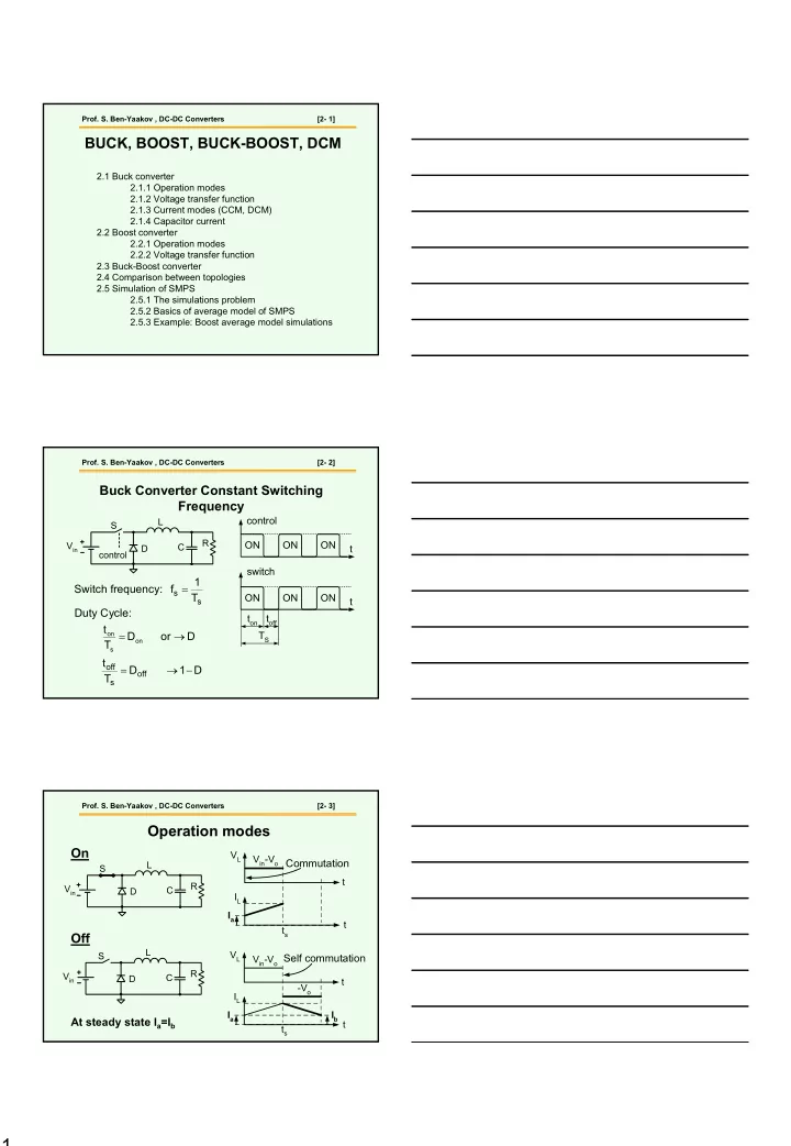
2.1 Buck converter 2.1.1 Operation modes 2.1.2 Voltage transfer function 2.1.3 Current modes (CCM, DCM) 2.1.4 Capacitor current 2.2 Boost converter 2.2.1 Operation modes 2.2.2 Voltage transfer function 2.3 Buck-Boost converter 2.4 Comparison between topologies 2.5 Simulation of SMPS 2.5.1 The simulations problem 2.5.2 Basics of average model of SMPS 2.5.3 Example: Boost average model simulations
BUCK, BOOST, BUCK-BOOST, DCM
- Prof. S. Ben-Yaakov , DC-DC Converters
[2- 2]
Buck Converter Constant Switching Frequency
t ON ON ON t ON ON ON control switch ton toff TS
s s
T 1 f = D
- r
D T t
- n
s
- n
→ = D 1 D T t
- ff
s
- ff
− → = Switch frequency: Duty Cycle:
S Vin D L C R control
- Prof. S. Ben-Yaakov , DC-DC Converters
[2- 3]
Operation modes
On Off
At steady state Ia=Ib
S Vin D L C R S Vin D L C R VL IL ts t Vin-Vo
- Vo