
SLIDE 1
4/12/2019 Atwood Comfort Control System 1
Agenda Introduction Overview of components Command Center Modes - - PowerPoint PPT Presentation
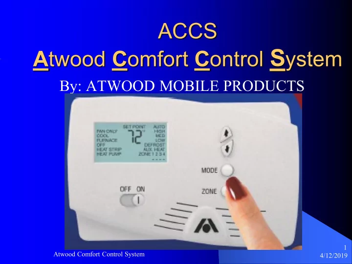
ACCS A twood C omfort C ontrol S ystem By: ATWOOD MOBILE PRODUCTS 1 Atwood Comfort Control System 4/12/2019 Agenda Introduction Overview of components Command Center Modes Of Operation Trouble Shooting 2 Atwood Comfort
4/12/2019 Atwood Comfort Control System 1
4/12/2019 Atwood Comfort Control System 2
4/12/2019 Atwood Comfort Control System 3
4/12/2019 Atwood Comfort Control System 4
The ACCS is used to manage the climate in each
4/12/2019 Atwood Comfort Control System 5
The ACCS is used to manage the climate in each vehicle by
4/12/2019 Atwood Comfort Control System 6
Command Center
4/12/2019 Atwood Comfort Control System 7
Control Board
4/12/2019 Atwood Comfort Control System 8
Control Board
4/12/2019 Atwood Comfort Control System 9
Remote Sensor
4/12/2019 Atwood Comfort Control System 10
RJ-45 Cable CAT-5
– TWISTED PAIR – SHIELDED
4/12/2019 Atwood Comfort Control System 11
Command Center Zone Control Communication Cable 12 VDC Low Voltage Connections 120 VAC High Voltage Connections Remote Thermistors Freeze Sensor No Ambient Sensor (RVP)
4/12/2019 Atwood Comfort Control System 12
4/12/2019 Atwood Comfort Control System 13
4/12/2019 Atwood Comfort Control System 14
4/12/2019 Atwood Comfort Control System 15
4/12/2019 Atwood Comfort Control System 16
The Command Center is the backbone of the
4/12/2019 Atwood Comfort Control System 17
4/12/2019 Atwood Comfort Control System 18
4/12/2019 Atwood Comfort Control System 19
4/12/2019 Atwood Comfort Control System 20
4/12/2019 Atwood Comfort Control System 21
4/12/2019 Atwood Comfort Control System 22
4/12/2019 Atwood Comfort Control System 23
4/12/2019 Atwood Comfort Control System 24
4/12/2019 Atwood Comfort Control System 25
4/12/2019 Atwood Comfort Control System 26
4/12/2019 Atwood Comfort Control System 27
– This mode is only available if the zone is equipped with an Atwood Excalibur XT 2-Stage Furnace.
4/12/2019 Atwood Comfort Control System 28
4/12/2019 Atwood Comfort Control System 29
4/12/2019 Atwood Comfort Control System 30
4/12/2019 Atwood Comfort Control System 31
4/12/2019 Atwood Comfort Control System 32
4/12/2019 Atwood Comfort Control System 33
4/12/2019 Atwood Comfort Control System 34
4/12/2019 Atwood Comfort Control System 35
4/12/2019 Atwood Comfort Control System 36
4/12/2019 Atwood Comfort Control System 37
4/12/2019 Atwood Comfort Control System 38
4/12/2019 Atwood Comfort Control System 39
4/12/2019 Atwood Comfort Control System 40
4/12/2019 Atwood Comfort Control System 41
AMBIENT REMOTE
4/12/2019 Atwood Comfort Control System 42
T (in F) R(k Ohms) 30 35.827 35 30.921 40 26.765 45 23.234 50 20.225 55 17.653 60 15.449 65 13.554 70 11.921 75 10.510 77 10.000 80 9.288 85 8.226 90 7.302 95 6.496 100 5.790 105 5.172 110 4.629 115 4.151 120 3.730 125 3.357
4/12/2019 Atwood Comfort Control System 43
LOCATION UNPLUGGED
– REVERTING TO COMMAND CENTER
4/12/2019 Atwood Comfort Control System 44
4/12/2019 Atwood Comfort Control System 45
1.
2.
3.
4.
5.
6.
4/12/2019 Atwood Comfort Control System 46
ERROR CODE MESSAGES:
4/12/2019 Atwood Comfort Control System 47
4/12/2019 Atwood Comfort Control System 48
4/12/2019 Atwood Comfort Control System 49
www.myrvworks.com
You can find more RV service manuals here: www.myrvworks.com/manuals
Over the years of running a mobile RV repair service, having a dedicated place to access service manuals for all the different appliances and components found on RVs was something that I always had a desire to create. I hope this resource makes your RV repairs easier, as it has mine, but please be careful and follow proper safety practices when attempting to repair your own RV. If in doubt, please consult with a professional RV technician! All service manuals provided on www.myrvworks.com are believed to be released for distribution and/or in the public domain.
DARREN KOEPP - OWNER, MY RV WORKS, INC.