
SLIDE 1
HTCMC - 9:
9th International Conference on High Temperature Ceramic Matrix Composites June 26 - July 1, 2016, Toronto, Canada Research Supported by the NASA Fundamental Aeronautics Program
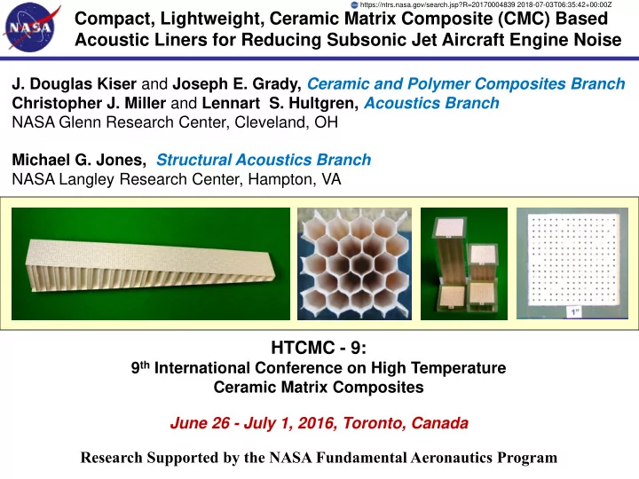
Compact, Lightweight, Ceramic Matrix Composite (CMC) Based Acoustic Liners for Reducing Subsonic Jet Aircraft Engine Noise
- J. Douglas Kiser and Joseph E. Grady, Ceramic and Polymer Composites Branch
Christopher J. Miller and Lennart S. Hultgren, Acoustics Branch NASA Glenn Research Center, Cleveland, OH Michael G. Jones, Structural Acoustics Branch NASA Langley Research Center, Hampton, VA
https://ntrs.nasa.gov/search.jsp?R=20170004839 2018-07-03T06:35:42+00:00Z