acknowledgm ents
play

Acknowledgm ents Effectiveness of Adjacent Funding Agencies: ODOT - PDF document

11/3/2015 Acknowledgm ents Effectiveness of Adjacent Funding Agencies: ODOT and Ohios Research Precast Concrete Box-Beam Initiative for Locals (ORIL) Connections ODOT SMEs: Dr. Waseem Khalifa, Mr. Perry Ricciardi, OTEC 2015 and Mr. Jim


  1. 11/3/2015 Acknowledgm ents Effectiveness of Adjacent Funding Agencies: ODOT and Ohio’s Research Precast Concrete Box-Beam Initiative for Locals (ORIL) Connections ODOT SMEs: Dr. Waseem Khalifa, Mr. Perry Ricciardi, OTEC 2015 and Mr. Jim Welter ORIL TAC: Mr. Steve Luebbe, Mr. Warren Schlatter, Mohamed Habouh and Ali Almonbhi - Graduate Students Anil Patnaik - Professor Mr. Jim Wiechart, and Dr. Eric Steinberg Department of Civil Engineering The contents in this presentation do not necessarily reflect the official views or policies of ODOT, ORIL, or FHWA. 2 
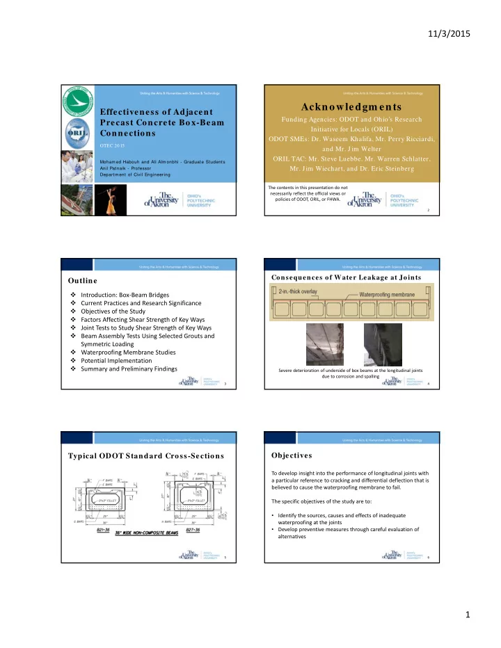
Consequences of Water Leakage at Joints Outline  Introduction: Box ‐ Beam Bridges  Current Practices and Research Significance  Objectives of the Study  Factors Affecting Shear Strength of Key Ways  Joint Tests to Study Shear Strength of Key Ways  Beam Assembly Tests Using Selected Grouts and Symmetric Loading  Waterproofing Membrane Studies  Potential Implementation  Summary and Preliminary Findings Severe deterioration of underside of box beams at the longitudinal joints due to corrosion and spalling 3 4 Typical ODOT Standard Cross-Sections Objectives To develop insight into the performance of longitudinal joints with a particular reference to cracking and differential deflection that is believed to cause the waterproofing membrane to fail. The specific objectives of the study are to: • Identify the sources, causes and effects of inadequate waterproofing at the joints • Develop preventive measures through careful evaluation of alternatives 5 6 1

  2. 11/3/2015 Tie Rods ‐ Key Way Geometries Joint Tests with Tie Rods Maria, Jubum, and Zi, PennDOT Report (May 2010) Failure of specimens with tie ‐ rod Russell Failure of specimens without tie ‐ rod The State of the Art of Precast/Prestressed Lateral cracks at the tie rod location (PCI 2011) occurred by de ‐ bonding of grout 7 8 Adjacent Box Beam Bridges (PCI 2009) for specimens with high tie force Key Way Geometries Joint Test Setup Joint Tests without Tie Rods 1.Key way geometry 2. Grout types 3. Effects of bond characteristics Bonding agent Cement slurry Sand blasting Shrinkage cracks 4. Improvement of Grout Performance 9 10 Summary of Test Results Effects of Key Way Geometry (Average first crack load) Vs. (key way geometry and grout material) Effect of Interface Length (Narrow) Effect of key way width (Partial depth) 40,000 Average first crack load (lb) 24,067 (422%) 35,000 40,000 40,000 37,000 (649%) First Cracking Load (lb) First Cracking Load (lb) 17,439 (306%) 35,000 35,000 30,000 17,167 (301%) 17,200 (302%) Partial / Narrow 15,950 (280%) 16,500 (289%) Partial / Narrow 14,833 (260%) 14,550 (255%) 34,700 (609%) 30,000 29,367 (515%) 30,000 25,000 12,500 (219%) 29,666 (526%) Partial / Wide Full / Narrow 25,000 25,000 8,800 (154%) 23,703 (416%) 20,000 8,333 (146%) 8,100 (142%) 6,400 (112%) 20,000 20,000 5,700 (100%) 6,167 (108%) 5,800 (102%) 5,200 (91%) 15,000 4,767 (84%) 5,033 (88%) 4,850 (85%) 5,300 (93%) 15,000 15,000 10,000 10,000 10,000 5,000 5,000 5,000 0 0 0 ODOT Magnesium Magnesium Polymer ODOT Approved Grout Magnesium Phosphate (1) Magnesium Phosphate (2) Polymer Grout ODOT Approved Grout Magnesium Phosphate (1) Magnesium Phosphate (2) Polymer Grout ODOT Approved Grout Magnesium Phosphate (1) Magnesium Phosphate (2) Polymer Grout Concrete (5,400 psi) ODOT Approved Grout Magnesium Phosphate (1) Magnesium Phosphate (2) Polymer Grout Concrete (5,400 psi) HSC (9786 psi) HSC (4282 psi) with Bonding Agent and Sand Blasted surface HSC (9786 psi) with Sand Blasted Surface UHPG ‐ Sand Blast UHPG ‐ Cement Slurry UHPG ‐ Sand Blast + Cement Slurry UHPG ‐ No Sand Blast ‐ No Cement Slurry ODOT Magnesium Magnesium Polymer HSC (4282 psi) with Bonding Agent Approved Phosphate Phosphate Grout Approved Phosphate Phosphate Grout Grout (1) (2) Grout (1) (2) Grout Material Grout Material Partial / Narrow keyway Full / Narrow keyway Partial / Wide keyway Full / Wide keyway Grout material / Key way geometry 11 12 2

  3. 11/3/2015 Surface Preparation Type: Sandblast / Cement Slurry / Effects of Surface Preparation Bonding Agent UHP Grout material Cement slurry Sandblast Normal and High Strength Concrete grout UHPG 40,000 40,000 Full / Wide X X Full / Wide UHP Grout First Cracking Load (lb) 35,000 35,000 28 day √ X Compressive X √ 30,000 strength = 19,100 30,000 First Cracking Load (lb) psi √ √ 25,000 25,000 20,000 20,000 15,000 15,000 10,000 10,000 Sand ‐ As ‐ cast blasted concrete 5,000 5,000 surface surface 0 0 Concrete HSC (9786 HSC (4282 HSC (4282 HSC (9786 No Sand Sand Cement Sand (5,400 psi) psi) psi) With psi) psi) Sand Blast, No Blast Slurry Blast, Bonding Bonding Blasted Agent Agent and Surface Cement Cement Sand Slurry Slurry Blasted Surface 13 14 Failure Modes Beam Assem bly Tests under Sym m etric Loading Six sets of three beams each • 1” tie rod at the ends of the beams through 2” • holes Debonding Mode • Torque of 250 ft ‐ lb (15 kips of clamping force) Observed in 48 test specimens which is the current practice • Vertical deflection, lateral movements, and the Failure through Concrete Units vertical movements were measured with LVDTs and • Observed for 11 specimens out of 12 in the dial gages Polymer • 6 specimens in the UHPG with sandblasting with • Strains in the rebar and on the concrete surface at and without cement slurry Failure through key way the top at mid ‐ span were recorded • And for 12 specimens in the HSC grout Observed in one specimen 15 16 with polymer grout Summary of Beam Assembly Tests Beam Assembly Tests (Sets # 1 and 2) The first two beam assemblies were grouted with ODOT standard key way geometry and approved grout 17 18 3

  4. 11/3/2015 Failure Loads of Beam Assemblies Test Setup for Sets #4, 5 and 6 Beam Assembly Test Results for Symmetric Loading 140,000 Cracking Load (lb) 120,000 100,000 80,000 60,000 40,000 20,000 0 ODOT Approved Sets #1 and 2 ODOT Approved Polymer Grout Set #3 ODOT Approved Set #4 High Strength Set #5 Polymer Grout Set #6 Grout Grout As ‐ Cast Concrete Grout Concrete As ‐ Cast Concrete As ‐ Cast Concrete As ‐ Cast Concrete Surface As ‐ Cast Concrete As ‐ Cast Concrete Surface ODOT Polymer Surface Surface Surface Surface Failed HSC ODOT Grout Grout Narrow, Set # 1 Set # 2 Set # 3 Set # 4 Set # 5 Set # 6 Specimen Wide, Deep ODOT Key Way Wide, Deep Deep Key Regrouted Key Way Key Way Way Load at 37 kips 121 kips 73 kips 107 kips 131 kips First Crack 19 20 Polymer Grout Condition After Typical Beam Failure Beam Assembly Tests (Set # 1 and 2) • Bond between the new grouts and the beam surfaces was excellent • It took lots of effort to separate the grout from the key ways • Joint failures were all local • Some of the beam units were used for regrouting and retesting 21 22 Waterproofing Membrane Studies Waterproofing Membranes Studied • The main objective in this part of the project was to evaluate Membrane # Type sheet membranes based on their ability to adhere to 1 Type III concrete, accommodate strains, and resist punching at the 2 SA, Not in ODOT QPL (Type II) same time provide waterproofing. 3 SA, Not in ODOT QPL (Type II) 4 Type III • Several Type II and Type III waterproofing membranes are 5 Type II included in ODOT QPL (qualified product list). SA refer to Self ‐ Adhesive (Type II) • Five different commercially available membranes were QPL refer to Qualified Product List studied in this study. 23 24 4

  5. 11/3/2015 Tensile Tests Tests Conducted on Waterproofing Mem branes • Five different systems were tested at different temperature 70 ° , 40 ° , 23 ° ,  Tensile tests at different temperatures 14 ° and –4 ° F  Adhesion tests • Each sample was conditioned in an environmental chamber at the  Differential deflection tests desired temperature for at least one  Punching tests hour.  Tests to detect initiation of leakage • More than 75 specimens were tested Dimensions in inches 25 26 Comparison of Tensile Strengths Comparison of Elongations at Different Temperatures 450 25.0 400 20.0 350 Elongation, % 300 #2 – SA Type II #2 – SA Type II 665 665 Load, lbf 15.0 250 #3 – SA Type II #3 – SA Type II ClodFlex ClodFlex 200 10.0 Polyguard #1 – Type III Polyguard #1 – Type III 150 Paveprep Paveprep #4 – Type III #4 – Type III 100 5.0 Paveprep SA Paveprep SA #5 – Type III #5 – Type III 50 0 0.0 70 40 23 14 ‐ 4 70 40 23 14 ‐ 4 Temperature, Degrees F Temperature, Degrees F 27 28 Adhesion Tests Adhesion Tests In order to measure the potential improvement of the application of • Adhesion is measured by heat to membrane for Type II SA membrane, three samples of three peeling strips of membrane strips were tested. Sealant is normally used for Type III at 380 degrees off of hardened mortar at F. 180°. • The test consists of adhering membranes to carefully 1. Samples subjected to direct heat with the use of sealant as prepared mortar block bonding agent. surfaces, cutting the 2. Sample with no heat application and with the use of sealant as membrane into one inch bonding agent. wide strips, and applying a 3. Sample with the use of direct heat and the use of primer as the tensile load at a constant rate of extension until each bonding agent, no sealant. strip peels off from the Dimensions in inches mortar blocks completely. The Sealant used was a “Hot ‐ Applied Modified Asphalt” Sealant. The primer was an “Asphalt Primer”. 29 30 5

Download Presentation
Download Policy: The content available on the website is offered to you 'AS IS' for your personal information and use only. It cannot be commercialized, licensed, or distributed on other websites without prior consent from the author. To download a presentation, simply click this link. If you encounter any difficulties during the download process, it's possible that the publisher has removed the file from their server.

Recommend


More recommend