OF A DENTAL COMPOSITE S. Setojima 1 , T. Watanuki 1 , K. Arakawa 2 * - - PDF document

of a dental composite
SMART_READER_LITE
LIVE PREVIEW

OF A DENTAL COMPOSITE S. Setojima 1 , T. Watanuki 1 , K. Arakawa 2 * - - PDF document

18 TH INTERNATIONAL CONFERENCE ON COMPOSITE MATERIALS LIGHT INTENSITY EFFECT ON POLYMERIZATION SHRINKAGE OF A DENTAL COMPOSITE S. Setojima 1 , T. Watanuki 1 , K. Arakawa 2 * M. Uchino 3 1 Graduate School, Kyushu University, Kasuga 816-8580, Japan 2


slide-1
SLIDE 1

18TH INTERNATIONAL CONFERENCE ON COMPOSITE MATERIALS

Abstract The shrinkage force resulting from polymerization

  • f a light-cured composite resin was measured using

a load cell and artificial cylindrical cavities. To study the effect of light intensity, we constructed cavities 4 mm in diameter with varying depths of 0.5 to 3.5

  • mm. The resin was poured into the cavity after

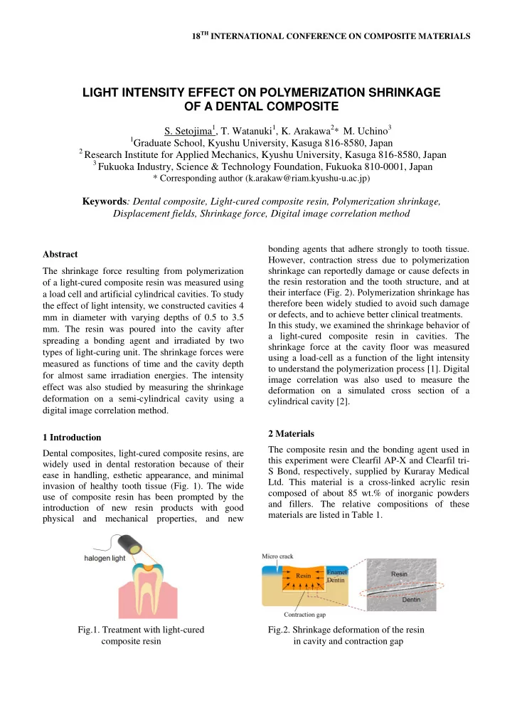
spreading a bonding agent and irradiated by two types of light-curing unit. The shrinkage forces were measured as functions of time and the cavity depth for almost same irradiation energies. The intensity effect was also studied by measuring the shrinkage deformation on a semi-cylindrical cavity using a digital image correlation method. 1 Introduction Dental composites, light-cured composite resins, are widely used in dental restoration because of their ease in handling, esthetic appearance, and minimal invasion of healthy tooth tissue (Fig. 1). The wide use of composite resin has been prompted by the introduction of new resin products with good physical and mechanical properties, and new bonding agents that adhere strongly to tooth tissue. However, contraction stress due to polymerization shrinkage can reportedly damage or cause defects in the resin restoration and the tooth structure, and at their interface (Fig. 2). Polymerization shrinkage has therefore been widely studied to avoid such damage

  • r defects, and to achieve better clinical treatments.

In this study, we examined the shrinkage behavior of a light-cured composite resin in cavities. The shrinkage force at the cavity floor was measured using a load-cell as a function of the light intensity to understand the polymerization process [1]. Digital image correlation was also used to measure the deformation on a simulated cross section of a cylindrical cavity [2]. 2 Materials The composite resin and the bonding agent used in this experiment were Clearfil AP-X and Clearfil tri- S Bond, respectively, supplied by Kuraray Medical

  • Ltd. This material is a cross-linked acrylic resin

composed of about 85 wt.% of inorganic powders and fillers. The relative compositions of these materials are listed in Table 1.

LIGHT INTENSITY EFFECT ON POLYMERIZATION SHRINKAGE OF A DENTAL COMPOSITE

  • S. Setojima1, T. Watanuki1, K. Arakawa2* M. Uchino3

1Graduate School, Kyushu University, Kasuga 816-8580, Japan

2 Research Institute for Applied Mechanics, Kyushu University, Kasuga 816-8580, Japan 3 Fukuoka Industry, Science & Technology Foundation, Fukuoka 810-0001, Japan

* Corresponding author (k.arakaw@riam.kyushu-u.ac.jp)

Keywords: Dental composite, Light-cured composite resin, Polymerization shrinkage, Displacement fields, Shrinkage force, Digital image correlation method

Fig.1. Treatment with light-cured Fig.2. Shrinkage deformation of the resin composite resin in cavity and contraction gap

slide-2
SLIDE 2

3 Experimental procedures 3.1 Shrinkage force measurement Figure 3 shows a schematic diagram of a testing device used to measure shrinkage force. This device consisted of a load cell clamped rigidly to a stainless steel base plate, a steel rod for connecting the load cell to the composite resin in the cavities, support rods and a brace for mounting a steel plate within the cavity. The plate was tightly clamped on the

  • brace. Cylindrical cavities were constructed with a

5-mm-thick plate with a hole 4 mm in diameter, and a steel rod 3.9 mm in diameter that was inserted from the backside of the plate. We used this metal because it adheres readily to the composite resin. To study the effect of the light intensity on the cavities, we varied the depth of the cavities from 0.5 to 3.5 mm, shifting the location of the steel rod. The specimens were prepared using the following procedures: (i) the bonding agent was applied to the cavities after cleaning with ethanol, (ii) the cavities were irradiated with a light-curing unit, (iii) the composite resin was then poured into the cavities and its surface was ground flat. In this experiment, the top surface was irradiated at 10-mm from the light source, as is a common procedure in clinical

  • practice. The shrinkage force was recorded over a

300-s period from the beginning of the irradiation. To study the effect of light intensity, we used two types of light-curing unit with a power of 1000 or 4000 mW/cm2. 3.2 Shrinkage deformation measurement Shrinkage deformations of the composites were measured using a semi-cylindrical cavity on a stainless steel plate. This geometry was used to simulate the cross section of the cylindrical cavity with 4 mm in diameter. The resin was filled into the semi-cylindrical cavities using the bonding agent according to the manufacturer’s instruction. Then the specimen surface to be measured was coated with black random pattern using a spray paint. The experimental setup for measuring the shrinkage behavior consisted of a CCD camera for taking the images of the specimen surface, and a computer to save the images. The camera was operated remotely via the computer to minimize the vibration due to clicking the shutter. The specimen was irradiated and the shrinkage behavior was recorded with the

  • camera. The simulated cross section was shield with

aluminum foil to prevent the undesired irradiation from the light tip. Table 1 Composite resin and bonding agent used in this study

product name material conformation composition monomer (Bis-GMA, TEGDEMA) filler (glass powder, silica micro filler), etc. monomer (Bis-GMA, MDP, HEMA) ethanol, water, etc. kuraray CLEARFIL AP-X kuraray CLEARFIL tri-S BOND resin past bonding agent liquid

Fig.3. Testing device for shrinkage force measurement. Fig.4. Shrinkage force P as functions of time and cavity depth (1000 mW/cm2 x 40 s).

slide-3
SLIDE 3

3 PAPER TITLE

4 Experimental results 4.1 Shrinkage force The shrinkage force P due to the polymerization was determined as a function of time t using the testing

  • device. Figure 4 shows three P-t diagrams for

different cavity depths h under the condition of irradiation energy (1000mW/cm2 x 40s). P for h=0.5 mm increased gradually with time, resulting in P=7 N at t=300 s. P for h=2.0 mm showed a steep increase compared to P for h=0.5 mm and yielded P=47 N at t=300 s, while P for h=3.0 mm decreased than P for h=2.0 mm. The experimental data that exhibited noticeable decreases in P following irradiation were not included due to damage or defects at the interface between the resin and the cavity. Figure 5 shows three P-t diagrams for different cavity depths h under the irradiation energy (4000 mW/cm2 x 9s). Similar to the low intensity 1000 mW/cm2, P increased during the irradiation stage and then gradually increased with t after the

  • irradiation. As h increased from 0.5 to 2.0 mm, P

increased greatly, whereas P decreased significantly for h=3.0 mm, resulting in a similar situation to the low intensity condition (Fig. 4). However, P under the high intensity 4000mW/cm2 yielded much smaller values for a given depth and almost constant energy (Fig. 5). Figure 6 plots the shrinkage force P* determined at 300 s after the start of the irradiation as a function of the cavity depth h to compare two results determined for the two intensity conditions. The values of P* for two conditions increased with h, reached their maximum values, and then decreased. Although there was scattering of the data, P* showed maximum values around h=2.3 mm. As described earlier, P was much smaller under the high intensity condition for a given cavity depth. This indicates that the intensity changes the flow of the resin from the top surface into the cavity floor and then caused displacement of the load cell. This result positively suggests that we can control the contraction stress at the interface between resin and tooth structure, thereby minimizing interfacial damage or defects in the cavities by changing the intensity. 4.1 Shrinkage deformation Figure 7 shows the shrinkage behavior of the resin

  • n the simulated cross-section in the cavities. The

deformations are demonstrated visually using the displacement vectors and color maps, and (a) shows the displacement fields under the irradiation intensity 1000mW/cm2 as a function of time, while (b) indicates the displacement fields under the intensity 4000mW/cm2. There are several interesting points in the shrinkage behavior. First, as demonstrated in (a) and (b), the centers of the shrinkage were initiated on the top free surfaces, i.e. the strongest area of the light intensity by the irradiation of the curing unit. Second, their deformations increased gradually from the top surfaces to the floor of the cavities. Finally, such a deformation of the center progressed faster in the high intensity condition for a given irradiation time. Fig.5. Shrinkage force P as functions of time and Fig.6. Shrinkage force P* after 300 s as a function cavity depth (4000 mW/cm2 x 9 s).

  • f cavity depth for two conditions.
slide-4
SLIDE 4
  • 5. Conclusions

The shrinkage force resulting from polymerization

  • f a light-cured composite resin was measured using

a load cell and artificial cylindrical cavities. To study the effect of light intensity, we constructed cavities 4 mm in diameter with varying depths of 0.5 to 3.5

  • mm. The resin was poured into the cavity after

spreading a bonding agent. For two irradiation conditions (1000mW/cm2 x 40 s) and (4000mW/cm2 x 9s), the shrinkage forces were measured as functions of time and the cavity depth. The intensity effect was also studied by measuring the shrinkage deformation on a semi-cylindrical cavity using a digital image correlation method, and the following results were obtained for almost same irradiation energy conditions: (1) The shrinkage force increased greatly during the irradiation stage and slightly increased following the irradiation. (2) The shrinkage force P* determined at 300 s increased, reached its maximum value, and then decreased as the cavity depth increased. (3) The shrinkage force was much smaller under the high intensity condition for a given cavity depth. (4) The shrinkage deformation was significantly larger under high intensity condition for a given irradiation time. Acknowledgments This work was supported by the Ministry of Education, Culture, Sports, Science and Technology (MEXT) Japan, as part of the “Highly-Functional Interfaces Science: Innovation of Biomaterials with Highly Functional Interface to Host and Parasite”

  • project. The authors would like to express Mr. Y.

Takahata from Kuraray Medical Ltd. for his useful advice and for supplying the materials. References

[1] K.

Arakawa “Shrinkage forces due to polymerization of light-cured dental composite resin in cavities”. Polymer Testing, Vol. 29, pp 1052-1056, 2010.

[2] T. Furukawa, K. Arakawa, Y. Morita, and M.

Uchino “Polymerization shrinkage behavior of light cure resin composites in cavities”. J.

  • Biomech. Sci. Eng. Vol. 4, No.3, pp 356-364,

2009. Fig.7. Displacement fields of resin filled in a semi-cylindrical cavity, (a) intensity: 1000 mW/cm2, (b) intensity: 4000 mW/cm2.