A U T O H I N G E A U T O H I N G E I N D E X Flag type series ( - - PDF document

a u t o h i n g e a u t o h i n g e i n d e x
SMART_READER_LITE
LIVE PREVIEW

A U T O H I N G E A U T O H I N G E I N D E X Flag type series ( - - PDF document

Cat.NO. K-114 NITTO KOHKI CO.,LTD. ISO 14001 JQA-EM4057 QC99J1026 NITTO KOHKI Co,.LTD. SHIRAKAWA NITTO KOHKI Co,.LTD. Headquarters/Research Center Nippori Office 122-T 143-T 1221 244-T 311S 112 122-AT 143-AT 733 113-PC 143-PC


slide-1
SLIDE 1

A U T O H I N G E

113-PC 143-PC 311S 244-PC 112 143-AT 122-AT 1221 122-T 143-T 244-T 733

A U T O H I N G E

NITTO KOHKI CO.,LTD. QC99J1026

SHIRAKAWA NITTO KOHKI Co,.LTD.

JQA-EM4057

NITTO KOHKI Co,.LTD. Headquarters/Research Center Nippori Office

ISO 14001

Cat.NO.K-114

slide-2
SLIDE 2

1

Flag type series (Table of models with specifications)

I N D E X

1111R 1111SR 1121R 1121SR 1211R 1211SR 1221R 1221SR 1110R 1120R 1210R 1220R 112R 112SR 122R-T 122SR-T 113R 113SR 113R TRISET 113SR TRISET 122R-AT 122SR-AT 132R 132SR 143R-T 143SR-T 143R-AT 143SR-AT 110R 120R-T 120R-AT 130R 140R-T 140R-AT 244R-T 244SR-T 240R-T 1111L 1111SL 1121L 1121SL 1211L 1211SL 1221L 1221SL 1110L 1120L 1210L 1220L 112L 112SL 122L-T 122SL-T 113L 113SL 113L TRISET 113SL TRISET 122L-AT 122SL-AT 132L 132SL 143L-T 143SL-T 143L-AT 143SL-AT 110L 120L-T 120L-AT 130L 140L-T 140L-AT 244L-T 244SL-T 240L-T Model number

Right hand opening 300 Series 1000 Series 100 Series 200 Series Empty hinge Empty hinge Left hand opening Door size applicable (mm)

H

(Max)

D

(Min)

W

(Max) 800 2000 30 30 Door weight (kg) (Max) Closing force (N•m) Stop mechanics Type of door Stop angle Max. Opening angle Color 5.0 7.9 10.0 85˚~180˚ 85˚ 85˚ 85˚ 85˚ 85˚ and 150˚ 85˚ and 150˚ 85˚ and 150˚ 85˚ and 150˚ 85˚ and 150˚ 85˚ and 150˚ 85˚ and 150˚ 85˚ and 150˚ 85˚ and 150˚ 180˚ Left or right one side opening 180˚ Left or right one side opening 180˚ Left or right one side opening 180˚ Left or right one side opening Silver Bronze Ivory Gold Bronze Bronze Bronze Bronze Silver Silver Silver Silver or Bronze Silver or Bronze Silver Silver Silver Silver 311S (Available for both right and left) 310 (Available for both right and left) Empty hinge Wood, aluminum (Indoor use) 850 2000 30 900 2100 900 2100 1000 2200 30 1200 2100 40 35 40 10.0 40 15.0 22.6 60 40 60 120 15.0 60 20.0 80 Wooden door Aluminum door Light steel door Wooden door Aluminum door Wooden door Light steel door (122T for steel frame) Wooden door Light steel door (122T for steel frame) Aluminum door Light steel door Partition door Aluminum door Light steel door Partition door Wooden door Light steel door (120T for steel frame) Steel door Steel door Steel door Empty hinge P.4 P.5 P.6 P.5 P.6 P.7 P.8 P.11 P.9 P.12 P.13 P.7 P.13 P.8 P.14 P.14 P.11 P.15 P.12 P.10
slide-3
SLIDE 3

2

733R 733SR 730R 113R-PC 113SR-PC 133R-PC 133SR-PC 143R-T-PC 143SR-T-PC 244R-T-PC 244SR-T-PC 110R-PC 130R-PC 140R-T-PC 240R-T-PC NK153R NK153SR NK153R TRISET NK153SR TRISET NK150R 733L 733SL 730L 113L-PC 113SL-PC 133L-PC 133SL-PC 143L-T-PC 143SL-T-PC 244L-T-PC 244SL-T-PC 110L-PC 130L-PC 140L-T-PC 240L-T-PC NK153L NK153SL NK153L TRISET

NK153SL TRISET

NK150L Model number

Right hand opening 700 Series PC Series 153 Series Empty hinge Empty hinge Left hand opening Door size applicable (mm)

H

(Max)

D

(Min)

W

(Max) 900 2100 40 120 Door weight (kg) (Max) Closing force (N•m) Stop mechanics Type of door Stop angle Max. Opening angle Color 15.0 15.0 22.6 15.0 85˚ and 150˚ 85˚ and 150˚ 85˚ and 150˚ 85˚ and 150˚ 85˚ and 150˚ 85˚ and 150˚ 85˚ and 150˚ 180˚ Left or right one side opening 180˚ Left or right one side opening Silver Silver 180˚ Left or right one side opening Silver Empty hinge Aluminum door Stainless door Steel door 900 2100 30 900 2100 30 1200 2100 40 40 40 60 60 120 900 2100 8 10 12 60 1000 2200 8 10 12 80 1000 2200 8 / 10 / 12 80 900 2100 40 120 Wooden door Aluminum door Light steel door Wooden door Light steel door Aluminum door Light steel door Aluminum door Light steel door Steel door Steel door Glass door

Each article is a combination of a spring hinge and a damper hinge (except for empty hinges). For opening orientation, each article designation gives an R to represent right-handed opening, and an L to represent left-handed opening. The opening orientation of the 300 series is for both right- and left-handed opening. The "S" in an article designation means that the product has a stop (with an internal stop mechanism). Every model with a -T or an -AT at the end of its article designation has a tap hole (M6) for installing it on a hinge flap. Nitto Kohki is ready to produce products of the same model but without such tap holes. (Examples: with tap hole, 143R-T; without tap hole, 143-R) The 300 and 1000 series with empty hinges are in packages of two pairs each,and the 100, 200, 700 and PC series come in packages of one pair each.

L R

Left & Right Hand Doors Left Hand Opening Right Hand Opening

P.17 P.19 P.20 P.21 P.22 P.19 P.20 P.21 P.22 P.23 P.24

slide-4
SLIDE 4

Simple design

Each model consists of a spring hinge and a damper hinge. This diagram represents the structure of the 100 series.

Comfort in a widening range of applications

Nitto Kohki's Auto Hinges of the flag type

They match all kinds of doors and make their images stand out beautifully. Table of applicable doors

The hinges double as door closers, thus giving the doors a neat-looking

  • finish. Their simple and beautiful designs match all kinds of doors.

They can also be used on arch doors that are not readily compatible with other door closers and doors with no head rails. The 100 and 200 series incorporate two springs (weak and strong) and a switching mechanism (clutch) for them, thus giving a small but sufficient door-closing power. The 300 series comes with an automatic mechanism for stopping closings at 85˚ to 180˚ (free stops), the 1000 series at 85˚, and the 100 and 200 series at 85˚ and 150˚. The speed can easily be adjusted with the mere use of a screwdriver.

These hinges are installed in exactly the same manner as conventional flag-type hinges. They do not require much labor. They are easy to handle.

They are so structured as to undergo little friction, thus achieving

  • utstanding durability.

3000

(mm) (mm)

2000 1500 1000 500 500 1000 1500 2500

200 series

(door weight: 120kg)

1000 series

(door weight: 35kg)

300 series

(door weight: 30kg)

100 series

(door weight: 40kg) (143T, 143AT door weight: 60kg)

Cap Spring pin Shaft Weak spring Ball bearing Ball bearing Clutch mechanism Adjusting screw Strong spring Cap Speed adjusting screw O-ring O-ring Piston Check valve Speed adjusting bar Cylinder

3

Flag type

300, 1000, 100, and 200 series

Spring hinge

(with an internal self-closing and stop mechanism)

Damper hinge

(with an internal control mechanism for closing speed)

A wide range of uses Sufficient door-closing power An internal stop mechanism Simple adjustment of closing speed Easy to install Outstanding durability

Door height Door width

slide-5
SLIDE 5

311S 310

Model Number Door Size Applicable (mm) H D W 800(Max) 2000(Max) 30(Max) 30(Min) Door Weight (kg) Surface Color Max. Opening Angle Location

  • f

Stop 5.0 85˚~180˚ 180˚ Left or Right One-side Opening Silver Bronze ivory gold

  • 1. Surface treatment is by a baked

coating of melamine resin.

  • 2. When using them on wooden

doors, use lauan or harder wood.

  • 3. The tapping screws furnished

with the products and designed specifically for installation are 25mm long. If the frame is wooden, use a frame at leas 25mm thick. If an aluminum, lightweight steel door is involved, use steel screws (flat screws M5).

  • 4. Allow at least 3mm of space

between outer edge of door and frame. Remarks

WOODEN DOORS-ALUMINIUM DOORS-STEEL DOORS

300series

Model 311S

Available for both righe-opening and left-opening doors.

In House Use

Over 13 Over 13 51 51 3.2 3.2 ø23 ø23 2 3.2 3.2 2

Wooden Doors Aluminium Doors Spring Hinge Damper Hinge

Preset Screw 8-ø6.3 Screw Hole

Cunter Sinking Diameter ø10.5 8-ø6.3 Screw Hole

Cunter Sinking Diameter ø10.5

3 3 15 15 41 41 153 41 19 19 19 51 51 102 9.5 9.5 3 3 15 15 41 41 153 41 ø23 51 51 102 9.5 19 9.5 ø23

EXTERNAL DIMENSIONS

Door

frame Empty Hinge

FITTING DIAGRAMS

Stop Mechanism Closeing Force (N•m)

4

slide-6
SLIDE 6

1111R 1111SR 1121R 1121SR 1110R 1120R 1111L 1111SL 1121L 1121SL 1110L 1120L

  • 1. The door and frame materials

to which the hinge is to be fitted should be of hard wood such as lauan or harder.

  • 2. Because the attached screws

for fitting are 25mm long, the thickness of the frame should be over 25mm.

  • 3. Allow at least 5mm of space

between outer edge of door and frame.

  • 4. Body material : Aluminum

Surface treatment : Silver(anodic oxide coating) Bronze(baked epoxy resin coating)

1000series

14 20 20 20 14 14 3.5 3.5 3.5 186.5 88 88 20 20 20 14 19 19 9.5 9.5 55 55 14 20 20 20 14 14 3.5 3.5 3.5 186.5 88 88 20 20 20 14 19 19 9.5 9.5 55 55 55 55 3.5 3.5 2 3.5 3.5 2

5

WOODEN DOORS-ALUMINIUM DOORS-STEEL DOORS

Model 1100

Over 14 Over 14 ø26 ø26 Spring Hinge Damper Hinge Spring Hinge Damper Hinge 8-ø6 Screw Hole

Cunter Sinking Diameter ø9.5

8-ø6 Screw Hole

Cunter Sinking Diameter ø9.5

EXTERNAL DIMENSIONS FITTING DIAGRAMS

ø26 ø26

Left Hand Door Right Hand Door

Hexagon Socket Head Screw L R

Left and Right Hand Doors

Left Hand Opening Right Hand Opening

Model Number Door Size Applicable(mm) H D W 850(Max) 2000(Max) 35(Max) 30(Min) Door Weight (kg) Surface Color Max. Opening Angle Location

  • f

Stop 85˚ 7.9 85˚ 180˚ Left or Right One-side Opening Silver Bronze Empty Hinge Right hand door Left hand door Silver Bronze

Remarks

Stop Mechanism Closeing Force (N•m)

slide-7
SLIDE 7

6

1211R 1211SR 1221R 1221SR 1210R 1220R 1211L 1211SL 1221L 1221SL 1210L 1220L

  • 1. For the wing fitting place on the

door and frame, a steel plate

  • f over 2.3mm thickness and

300mm length must be used as a reinforcing material.

  • 2. Use the screws included in

package for installation.

  • 3. Allow at least 5mm of space

between outer edge of door and frame.

  • 4. Body material : Aluminum

Surface treatment : Silver(anodic oxide coating) Bronze(baked epoxy resin coating)

For Surface Mounted 55 1 3.5 14 20 20 20 14 14 3.5 3.5 3.5 186.5 88 88 20 20 20 14 19 19 9.5 9.5 55 55 14 20 20 20 14 14 3.5 3.5 3.5 186.5 88 88 20 20 20 14 19 19 9.5 9.5 55 55 55 1 3.5

1000series

WOODEN DOORS-ALUMINIUM DOORS-STEEL DOORS

Model 1200

Over 14 Over 14 Spring Hinge Damper Hinge Spring Hinge Damper Hinge 8-ø6 Screw Hole

Cunter Sinking Diameter ø9.5

8-ø6 Screw Hole

Cunter Sinking Diameter ø9.5

EXTERNAL DIMENSIONS FITTING DIAGRAMS

ø26 ø26 ø26 ø 2 6

Left Hand Door Right Hand Door

Model Number Door Size Applicable(mm) H D W 850(Max) 2000(Max) 35(Max) 30(Min) Door Weight (kg) Surface Color Max. Opening Angle Location

  • f

Stop 7.9 85˚ 85˚ 180˚ Left or Right One-side Opening Silver Bronze Empty Hinge Right hand door Left hand door Silver Bronze Hexagon Socket Head Screw L R Left and Right Hand Doors

Left Hand Opening Right Hand Opening

Remarks

Stop Mechanism Closeing Force (N•m)

slide-8
SLIDE 8

7

112R 112SR 110R 112L 112SL 110L

  • 1. The door and frame materials

to which the hinge is to be fitted should be of hard wood such as lauan or harder.

  • 2. Because the attached screws

for fitting are 25mm long, the thickness of the frame should be over 25mm.

  • 3. Allow at least 5mm of space

between outer edge of door and frame.

  • 4. The R type is also available for

the corner of blade.

  • 5. Surface treatment is by a baked

coating of melamine resin.

  • 6. Always allow for a door stopper

to prevent the door from

  • pening wider than 180˚.

60 60 3 3 (9.5) (9.5) 2 198 95 95 19 19 19 19 19 19 19 19 (9.5) 19 9.5 60 60 19 9.5 9.5 9.5 3 3

9.5 9.5

2 198 95 95 19 19 19 19 19 19 19 19 (9.5) 19 9.5 60 60 19 9.5 4 4 1.6 4 4 1.6

L L L L R R R R

100series

WOODEN DOORS-ALUMINIUM DOORS-STEEL DOORS

Model 112

Over 17 Over 17 Spring Hinge Damper Hinge Spring Hinge Damper Hinge 10-ø7 Screw Hole

Cunter Sinking Diameter ø10.5

10-ø7 Screw Hole

Cunter Sinking Diameter ø10.5

EXTERNAL DIMENSIONS FITTING DIAGRAMS

ø 3 2 ø32 ø32 ø32

Left Hand Door Right Hand Door

L R Left and Right Hand Doors

Left Hand Opening Right Hand Opening

Model Number Door Size Applicable(mm) H D W 900(Max) 2100(Max) 40(Max) 30(Min) Door Weight (kg) Surface Color Max. Opening Angle Location

  • f

Stop 85˚ & 150˚ 10.0 180˚ Left or Right One-side Opening Empty Hinge Right hand door Left hand door Silver & Bronze

Remarks

Preset Screw Stop Mechanism Closeing Force (N•m)

slide-9
SLIDE 9

8

122R-T 122SR-T 120R-T 122L-T 122SL-T 120L-T

H D W

For Steel Frame

60 60 4 4 8.3 4 4 8.3 3 3 (9.5) 2 198 95 95 19 19 19 19 19 9.5 19 19 19 (9.5) 19 9.5 9.5 60 60 19 9.5 5-M6X1 5-M6X1 3 3 (9.5) 2 198 95 95 19 19 19 19 19 9.5 19 19 19 (9.5) 19 9.5 9.5 60 60 19 9.5 7 .5 7 .5

L L L L R R R R R L L L R R

R10 R10 R10 R10

100series

WOODEN DOORS-ALUMINIUM DOORS-STEEL DOORS

Model 122T

Over 17 Over 17 Spring Hinge Damper Hinge Spring Hinge Damper Hinge 5-ø7 Screw Hole

Cunter Sinking Diameter ø10.5

5-ø7 Screw Hole

Cunter Sinking Diameter ø10.5

EXTERNAL DIMENSIONS FITTING DIAGRAMS

ø32 ø32 ø32 ø 3 2

Left Hand Door Right Hand Door

Model Number Door Size Applicable(mm) H D W 900(Max) 2100(Max) 40(Max) 30(Min) Door Weight (kg) Stop Mechanism Closeing Force (N•m) Surface Color Max. Opening Angle Location

  • f

Stop 10.0 85˚ & 150˚ 180˚ Left or Right One-side Opening Silver Empty Hinge Right hand door Left hand door Hexagon Socket Head Screw L R Left and Right Hand Doors

Left Hand Opening Right Hand Opening
  • 1. For the blade fitting place on

the frame, a steel plate of over 2.3mm thickness and 300mm length must be used as a reinforcing material.

  • 2. For the blade fitting on the

frame, use M6 flat screw. (Avoid installation by welding.)

  • 3. For the blade fitting place on

the door use a hard wood such as lauan or harder.

  • 4. Allow at least 5mm of space

between at outer edge of door and frame.

  • 5. Surface treatment is by a baked

coating of melamine resin.

  • 6. Always allow for a door stopper

to prevent the door from

  • pening wider than 180˚.

Remarks

Protection Cover Protection Cover

slide-10
SLIDE 10

9

113R 113SR 110R 113L 113SL 110L

  • 1. The door and frame materials

to which the hinge is to be fitted should be of hard wood such as lauan or harder.

  • 2. Because the attached screws

for fitting are 25mm long, the thickness of the frame should be over 25mm.

  • 3. Allow at least 5mm of space

between outer edge of door and frame.

  • 4. The edge type is also available

for the corner of leaves.

  • 5. Surface treatment is by a baked

coating of melamine resin.

  • 6. Always allow for a door stopper

to prevent the door from

  • pening wider than 180˚.

100series

WOODEN DOORS

Model 113

Spring Hinge Damper Hinge Spring Hinge Damper Hinge

EXTERNAL DIMENSIONS FITTING DIAGRAMS

Left Hand Door Right Hand Door

L R Left and Right Hand Doors

Left Hand Opening Right Hand Opening

Model Number Door Size Applicable(mm) H D W 900(Max) 2100(Max) 60(Max) 30(Min) Door Weight (kg) Surface Color Max. Opening Angle Location

  • f

Stop 85˚ & 150˚ 15.0 180˚ Left or Right One-side Opening Empty Hinge Right hand door Left hand door Silver

Remarks

Stop Mechanism Closeing Force (N•m) 3 3 9.5 2 198 95 95 19 19 19 19 19 19 19 19 9.5 19 9.5 60 60 Over 17 Over 17 60 60

ø 3 2 ø32 19 9.5 3 3 9.5 2 198 95 95 19 19 19 19 19 19 19 19 9.5 19 9.5 60 60 ø32 19 9.5 10-ø7 Screw Hole

Counter Sinking Diameter ø10.5

10-ø7 Screw Hole

Counter Sinking Diameter ø10.5

Shaft Holding Screw R10 R10 R10 R10 R10 R10 R10 R10 4 4 1.6 4 4 1.6 ø 3 2

slide-11
SLIDE 11

10

113R (TRI-SET) 113SR (TRI-SET) 113L (TRI-SET) 113SL (TRI-SET)

H D W

100series

WOODEN DOORS

Model 113 (TRI-SET)

Spring Hinge Damper Hinge Spring Hinge Damper Hinge

EXTERNAL DIMENSIONS FITTING DIAGRAMS

Left Hand Door Right Hand Door

Model Number Door Size Applicable(mm) H D W 1000(Max) 2200(Max) 80(Max) 30(Min) Door Weight (kg) Stop Mechanism Closeing Force (N•m) Surface Color Max. Opening Angle Location

  • f

Stop 20.0 85˚ & 150˚ 180˚ Left or Right One-side Opening Silver Right hand door Left hand door L R Left and Right Hand Doors

Left Hand Opening Right Hand Opening
  • 1. The door and frame materials

to which the hinge is to be fitted should be of hard wood such as lauan or harder.

  • 2. Because the attached screws

for fitting are 30mm long, the thickness of the frame should be over 30mm.

  • 3. Allow at least 5mm of space

between outer edge of door and frame.

  • 4. The edge type is also available

for the corner of leaves.

  • 5. Surface treatment is by a baked

coating of melamine resin.

  • 6. Always allow for a door stopper

to prevent the door from

  • pening wider than 180˚.

Remarks

3 3 9.5 2 198 95 95 19 19 19 19 19 19 19 19 9.5 19 9.5 60 R10 R10 60 Over 17 Over 17 60 60 ø 3 2 ø32 19 9.5 R10 R10 R10 R10 R10 R10 3 3 9.5 2 198 95 95 19 19 19 19 19 19 19 19 9.5 19 9.5 60 60 ø32 19 9.5 10-ø7 Screw Hole

Counter Sinking Diameter ø10.5

10-ø7 Screw Hole

Counter Sinking Diameter ø10.5

Shaft Holding Screw 4 4 1.6 4 4 1.6 ø 3 2 Left Hand Door Right Hand Door DH DH/2 100 200 DH/2 Installation Damper Hinge Sprng Hinge Spring Hinge

slide-12
SLIDE 12

11

122R-AT 122SR-AT 120R-AT 122L-AT 122SL-AT 120L-AT

H D W

  • 1. For the blade fitting place on

the frame, a steel plate of over 2.3mm thickness and 300mm length must be used as a reinforcing material.

  • 2. For the blade fitting on the

frame, use M6 flat screw. (NOT include) dimension can be used. when cut the blade. (Avoid installation by welding.)

  • 3. For the blade fitting place on

the door use a hard wood such as lauan or harder.

  • 4. Allow at least 5mm of space

between at outer edge of door and frame.

  • 5. Surface treatment is by a baked

coating of melamine resin.

  • 6. Always allow for a door stopper

to prevent the door from opening wider than 180˚.

60 60 4 4 8.3 4 4 8.3 7 .5 7 .5 15 65 35 (15)

L

ø32 60 60 24 16 6 6-M6X1 6-M6X1

L R

15 15 15 65 35 (15)

L

ø32 60 60 24 16 6

L

15 15

R

3 3 (9.5) 2 198 95 95 19 19 19 19 19 9.5 9.5

L R R L

3 3 (9.5) 2 198 95 95 19 19 19 19 19 9.5 9.5

L

R10 R10 R10 R10

100series

Model 122AT

Spring Hinge Damper Hinge Spring Hinge Damper Hinge

EXTERNAL DIMENSIONS FITTING DIAGRAMS

Left Hand Door Right Hand Door

L R Left and Right Hand Doors

Left Hand Opening Right Hand Opening

Model Number Door Size Applicable(mm) H D W 900(Max) 2100(Max) 40(Max) 30(Min) Door Weight (kg) Surface Color Max. Opening Angle Location

  • f

Stop 85˚ & 150˚ 180˚ Left or Right One-side Opening Empty Hinge Right hand door Left hand door Silver

Remarks

Stop Mechanism 10.0 Closeing Force (N•m)

For Steel Frame

WOODEN DOORS-ALUMINIUM DOORS-STEEL DOORS

Over 17 Over 17 5-ø7 Screw Hole

Cunter Sinking Diameter ø10.5

5-ø7 Screw Hole

Cunter Sinking Diameter ø10.5

ø32 ø32

Hexagon Socket Head Screw

Protection Cover Protection Cover

slide-13
SLIDE 13

12

132R 132SR 130R 132L 132SL 130L

  • 1. For the wing fitting place on the

door and frame, a steel plate

  • f over 2.3mm thickness and

300mm length must be used as a reinforcing material.

  • 2. Use the screws included in

package for installation.

  • 3. Allow at least 5mm of space

between outer edge of door and frame.

  • 4. Surface treatment is by a baked

coating of melamine resin.

  • 5. Always allow for a door stopper

to prevent the door from

  • pening wider than 180˚.

3 3 (9.5) 2 198 95 95 19 19 19 19 19 19 19 19 (9.5) 19 9.5 60 60 19 9.5 3 3 (9.5) 2 198 95 95 19 19 19 19 19 19 19 19 (9.5) 19 9.5 60 60 19 9.5

L L L L R R R R

1 60 4 60 1 4

9.5 9.5

9.5 9.5

100series

Model 132

Spring Hinge Damper Hinge Spring Hinge Damper Hinge

EXTERNAL DIMENSIONS FITTING DIAGRAMS

Left Hand Door Right Hand Door

Model Number Door Size Applicable(mm) H D W 900(Max) 2100(Max) 40(Max) 30(Min) Door Weight (kg) Stop Mechanism Surface Color Max. Opening Angle Location

  • f

Stop 85˚ & 150˚ 180˚ Left or Right One-side Opening Silver Empty Hinge Right hand door Left hand door L R Left and Right Hand Doors

Left Hand Opening Right Hand Opening

Remarks

Over 17 Over 17 ø32 ø32 ø32 10-ø7 Screw Hole

Counter Sinking Diameter ø10.5

10-ø7 Screw Hole

Counter Sinking Diameter ø10.5

Shaft Holding Screw ø 3 2

ALUMINIUM DOORS-STEEL DOORS

10.0 Closeing Force (N•m) For Surface Mounted

slide-14
SLIDE 14

13

143R-T 143SR-T 140R-T 143L-T 143SL-T 140L-T

  • 1. For the blade fitting place on

the door and frame, a steel plate of over 2.3mm thickness and 300mm length must be used as a reinforcing material.

  • 2. For the blade fitting on the door

and frame, use M6 flat screw X5 pcs. (Avoid installation by welding.)(not include)

  • 3. In case of applying to a fire

protection door, use the model (143R, 143L) without a stop.

  • 4. Allow at least 5mm of space

between at outer edge of door and frame.

  • 5. Surface treatment is by a baked

coating of melamine resin.

  • 6. Always allow for a door stopper

to prevent the door from

  • pening wider than 180˚.

3 3 (9.5) 2 198 95 95 19 19 19 19 19 9.5 19 19 19 (9.5)

19

9.5

9.5

60 60 ø32 ø32 19 9.5 10-M6X1 10-M6X1 3 3 (9.5) 2 198 95 95 19 19 19 19 19 9.5 19 19 19 (9.5) 19 9.5 9.5 60 60 19 9.5 60 60 4 4 15 4 4 15

L L R R L L R R

R10 R10 R10 R10 R10 R10 R10 R10

100series

Model 143T

Spring Hinge Damper Hinge Spring Hinge Damper Hinge

EXTERNAL DIMENSIONS FITTING DIAGRAMS

Left Hand Door Right Hand Door

L R Left and Right Hand Doors

Left Hand Opening Right Hand Opening

Model Number Door Size Applicable(mm) H D W 900(Max) 2100(Max) 60(Max) 30(Min) Door Weight (kg) Surface Color Max. Opening Angle Location

  • f

Stop 85˚ & 150˚ 180˚ Left or Right One-side Opening Empty Hinge Right hand door Left hand door Silver

Remarks

Stop Mechanism 15.0 Closeing Force (N•m)

STEEL DOORS

Over 17 Over 17 ø32 ø32

Hexagon Socket Head Screw

Protection Cover Protection Cover

slide-15
SLIDE 15

14

143R-AT 143SR-AT 140R-AT 143L-AT 143SL-AT 140L-AT 60 4 4 15 60 4 4 15 15 65 35 15

L

3 3 198 95 95 15 15 65 6

L

2 60 60 24 16 6

L R

15 15 16 24 15 15 35 15 65 35 15

L

3 3 198 95 95 15 15 65 6

L

2 60 60 24 16 6

L

15 15 16 24 15 15 35

R R R

R10 R10 R10 R10 R10 R10 R10 R10

  • 1. For the blade fitting place on

the frame, a steel plate of over 2.3mm thickness and 300mm length must be used as a reinforcing material.

  • 2. For the blade fitting on the

frame, use M6 flat screwX5

  • pcs. (NOT include)

dimension can be used. when cut the blade. (Avoid installation by welding.)

  • 3. For the blade fitting place on

the door use a hard wood such as lauan or harder.

  • 4. Allow at least 5mm of space

between at outer edge of door and frame.

  • 5. Surface treatment is by a baked

coating of melamine resin.

  • 6. Always allow for a door stopper

to prevent the door from opening wider than 180˚.

ø32 ø32 12-M6X1 12-M6X1

100series

Model 143AT

Spring Hinge Damper Hinge Spring Hinge Damper Hinge

EXTERNAL DIMENSIONS FITTING DIAGRAMS

Left Hand Door Right Hand Door

L R Left and Right Hand Doors

Left Hand Opening Right Hand Opening

Model Number Door Size Applicable(mm) H D W 900(Max) 2100(Max) 60(Max) 30(Min) Door Weight (kg) Surface Color Max. Opening Angle Location

  • f

Stop 85˚ & 150˚ 180˚ Left or Right One-side Opening Empty Hinge Right hand door Left hand door Silver

Remarks

Stop Mechanism 15.0 Closeing Force (N•m)

STEEL DOORS

Over 17 Over 17 ø32 ø32

Hexagon Socket Head Screw

Protection Cover Protection Cover

slide-16
SLIDE 16

15

200series

Model 244T

Spring Hinge Damper Hinge Spring Hinge Damper Hinge

EXTERNAL DIMENSIONS FITTING DIAGRAMS

Left Hand Door Right Hand Door

L R Left and Right Hand Doors

Left Hand Opening Right Hand Opening

Model Number Door Size Applicable(mm) H D W 1200(Max) 2100(Max) 120(Max) 40(Min) Door Weight (kg) Surface Color Max. Opening Angle Location

  • f

Stop 85˚ & 150˚ 180˚ Left or Right One-side Opening Empty Hinge Right hand door Left hand door Silver

Remarks

Stop Mechanism 22.6 Closeing Force (N•m)

STEEL DOORS

Over 20 Over 20

Hexagon Socket Head Screw

244R-T 244SR-T 240R-T 244L-T 244SL-T 240L-T

  • 1. For the blade fitting place on

the door and frame, a steel plate of over 3.2mm thickness and 300mm length must be used as a reinforcing material.

  • 2. For the blade fitting on the door

and frame, use M6 flat screw X6 pcs. (Avoid installation by welding.)(Not include)

  • 3. In case of applying to a fire

protectiondoor, use the model (244R-T, 244L-T) without a stop.

  • 4. Allow at least 5mm of space

between at outer edge of door and frame.

  • 5. Surface treatment is by a baked

coating of melamine resin.

  • 6. Always allow for a door stopper

to prevent the door from

  • pening wider than 180˚.

ø34.5 ø34.5 65 65 (10) 47 .5 47 .5 10 10 47 .5 47 .5 (10) 4 239 3 115 115 2 8 8 26 26 65 65 ø34.5 ø34.5 (10) 47 .5 47 .5 10 10 47 .5 47 .5 (10) 4 239 3 115 115 2 8 8 26 26 12-M6X1 12-M6X1 65 65 16 5 5 16 5 5

L L R R L L R R

R10 R10 R10 R10 R10 R10 R10 R10

slide-17
SLIDE 17

13

They come with special sealing and stainless steel.

A much wider range of uses including bathrooms and seashores.

They blend in with exterior and interior products and make their images stand out beautifully.

L L L L

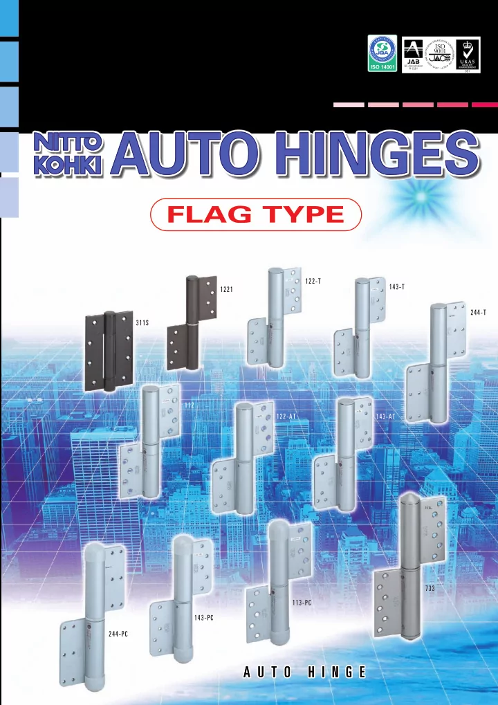
Stainless steel, flag type

700 series

16

Simple design

The hinges double as door closers, thus giving the doors a neat-looking

  • finish. Their simple and beautiful designs match all kinds of doors.

Spring hinge A wide range of uses

They meet an even wider range of uses of the flag type. They can be used in bathrooms, seashores and other environments.

Outstanding durability

Their low-friction structure achieves outstanding durability.

An internal stop mechanism

They come with an internal stop mechanism that stops the door automatically at 85˚ and 150˚.

Simple adjustment of closing speed

The door-closing speed can easily be set and changed with the mere use of a normal screwdriver.

No need of adjusting the door-closing speed

They come with an internal actuator with a temperature sensor. You have only to set the door-closing speed (at a desired setting) initially, and you can keep the door-closing speed constant without being affected by the ambient temperature.

They are compatible with the stainless steel used in exterior products Easy to install

They are installed in exactly the same manner as ordinary flag type hinges. They do not require much labor and are easy.

Dew-proofed by a special sealing structure Life extended by special surface treatment

About twice as durable as the Auto Hinge of the PC type (at least 200,000 openings and closings)

They are made of stainless steel for high corrosion resistance.

About three times as corrosion-proof as the Auto Hinge of the PC type (at least 500 hours in a salt spray test) (with an internal self-closing and stop mechanism)

Damper hinge

(with an internal closing speed control mechanism with a temperature compensator) Cap sealing structure Cap sealing structure With special rubber sealing Stainless steel used Stainless steel used Stainless steel used Sealing structure

With an internal temperature sensor

Stainless steel used Stainless steel used Stainless steel used

Double cylinder structure Backlash reduction mechanism

Clutch mechanism O-ring

Specially rust-proof plated Specially rust-proof plated Specially rust-proof plated Each model consists of a spring hinge and a damper hinge. This diagram represents the structure of the 700 series.

Table of doors applicable to the Auto Hinge 733

1000 500 2000 1000 2500

Door height (mm) Door width (mm)

Model 733

(door weight: 120kg)

slide-18
SLIDE 18

17

700series

Model 733

Spring Hinge Damper Hinge Spring Hinge Damper Hinge

EXTERNAL DIMENSIONS FITTING DIAGRAMS

Left Hand Door Right Hand Door

L R Left and Right Hand Doors

Left Hand Opening Right Hand Opening

Model Number Door Size Applicable(mm) H D W 900(Max) 2100(Max) 120(Max) 40(Min) Door Weight (kg) Surface Color Max. Opening Angle Location

  • f

Stop 85˚ & 150˚ 180˚ Left or Right One-side Opening Empty Hinge Right hand door Left hand door stain

Remarks

Stop Mechanism 15.0 Closeing Force (N•m) Over 20 Over 20 Hexagon Socket Head Screw Protection Cover Protection Cover

ALUMINIUM DOORS-STAINLESS STEEL DOORS-STEEL DOORS

12-ø7 Screw Hole

Cunter Sinking Diameter ø10.5

12-ø7 Screw Hole

Cunter Sinking Diameter ø10.5

733R 733SR 730R 733L 733SL 730L 9

(11)

19 19 19 19 19 19 19 9.5

  • 1. Surface treatment is by a baked

coating of acrylic resin on the stainless steel.

  • 2. On the mounts of the flaps for both

the door and frame, always use a reinforcing steel plate at least 3.2mm and 300mm long. Fix the reinforcement directly on the framework.

  • 3. They come with flat head screws

M5 x 16L (P = 0.8) as mounting screws.

  • 4. Always allow for a clearance of at

least 5mm for the door.

  • 5. Always allow for a door stopper to

prevent the door from opening wider than 180˚.

  • 6. Avoid using them in sauna rooms.

65 65 ø34.5 9 4

(11)

19 19 19 19 19 13 13 115 115 9.5

L L R R

9

(11)

19 19 19 19 19 19 19 9.5 65 65 ø34.5 9 4

(11)

19 19 19 19 19 13 13 115 115 9.5

L R

ø34.5 65 4 1 ø 3 4 . 5 65 4 1

L R This hinge has been factori-adjusted to about 10mm clearance left between both leaves to provide temperature compensation funcion. In hinge installation, adjust the clearance at site so that it will be reduced to 4mm.
slide-19
SLIDE 19

18

Constant speed of door closing!

Various functions (automatic temperature compensation and drip-proofing) in a slim body

These hinges make entrance doors and outdoor doors look neat.

Spring hinge

(with an internal self-closing and stop mechanism)

Damper hinge

(with an internal closing speed control mechanism with a temperature compensator)

Flag type

PCseries

Actuator with a temperature sensor

They achieve high reliability in severe outdoor environments.

L L

With an internal temperature sensor Backlash reduction mechanism

L L

Special rust-proof plated Double coated Cover cap used

Model 100PC

Models 113 and 133PC (door weight: 40kg) Model 143PC (door weight: 60kg)

Model 200 PC

(door weight: 120kg)

3000 2000 1000

Table of doors applicable to Auto Hinges PC series

1000 500

(mm)

Door height

(mm)

Door width Each model consists of a spring hinge and a damper hinge. This diagram represents the structure of the PC series.

Simple design

The hinges double as door closers, thus giving the doors a neat-looking

  • finish. Their simple and beautiful designs match all kinds of doors.

Drip-proof types that withstand outdoor use

Being drip-proof, they can be used for entrance doors exposed to outside air and gate doors exposed directly to rain.

Easy to set the door-closing speed

The door-closing speed can easily be set and changed with the mere use of a normal screwdriver.

Easy to install and handle

They are handled in exactly the same manner as the company's standard Auto Hinge, flag type, 100 and 200 series.

Outstanding durability

They are so structured as to produce little friction, thus achieving

  • utstanding durability.

Equipped with an internal stop mechanism

TThey come with an internal stop mechanism for causing the door to close itself and stop at 85˚ and 150˚.

No need to adjust door-closing speed

On the PC series with an internal actuator with a temperature sensor, you have only to set the door-closing speed (at a desired setting) initially. The hinges will then maintain the door closing speed without being affected by the ambient temperature.

slide-20
SLIDE 20

113R-PC 113SR-PC 110R-PC 113L-PC 113SL-PC 110L-PC

H D W

Optional Color

100PCseries Model 113-PC

Over 19

60 4 1.6 4 R R

Over 19

60 4 1.6 4

15 95 3 223 9.5 9.5 19 19 19 19 95 19 (9.5) 15 (9.5)

L L

19 19 19 19 19 9.5 9.5 ø32 60 60

R R

15 95 3 223 9.5 9.5 19 19 19 19 95 19 (9.5) 15 (9.5)

L L

19 19 19 19 9.5 19 9.5 ø32 60 60 Spring Hinge Spring Hinge

ø35 ø35 Model Number Door Size Applicable(mm) Door Weight (kg) Surface Color Max. Opening Angle Location
  • f

Stop Right hand door Left hand door Stop Mechanism Closeing Force (N•m) Empty Hinge 900(Max) 2100(Max) 40(Max) 30(Min) 85˚ & 150˚ 180˚ Left or Right One-side Opening 15.0

EXTERNAL DIMENSIONS

Left Hand Door Right Hand Door

Hexagon Socket Head Screw

Damper Hinge Damper Hinge

This hinge has been factori-adjusted to about 10mm clearance left between both leaves to provide temperature compensation funcion. In hinge installation, adjust the clearance at site so that it will be reduced to 3mm.

FITTING DIAGRAMS

10-ø7 Screw Hole

Cunter Sinking Diameter ø10.5

10-ø7 Screw Hole

Cunter Sinking Diameter ø10.5 L R Left and Right Hand Doors

Left Hand Opening Right Hand Opening

Remarks

  • 1. Surface treatment is by a baked

coating of acrylic resin.

  • 2. For the flap mounts on the door

and frame, be sure to use a steel plate at least 2.3mm thick and 300mm long made of lauan or harder wood or reinforcement. Fix the reinforcement directly on the framework.

  • 3. They come with mounting tapping

screws 25mm long. Use a frame at least 25mm.

  • 4. Allow for a door clearance of at

least 5mm.

  • 5. Always allow for a door stopper to

prevent the door from opening wider than 180˚.

WOODEN DOORS-ALUMINIUM DOORS-STEEL DOORS

Silver Black Bronze Tapping Screw

ø5x25 (SUS)

Tapping Screw

ø5x25 (SUS)

19

slide-21
SLIDE 21

20

Model 133-PC

60

Over 19

ø35 4 1 60

Over 19

ø35 4 1 R R

15 95 3 223 9.5 9.5 19 19 19 19 95 19 (9.5) 15 (9.5)

L L

19 19 19 19 19 9.5 9.5 ø32 60 60

R R

15 95 3 223 9.5 9.5 19 19 19 19 95 19 (9.5) 15 (9.5)

L L

19 19 19 19 9.5 19 9.5 ø32 60 60 133R-PC 133SR-PC 130R-PC 133L-PC 133SL-PC 130L-PC H D W

100PCseries

Model Number Door Size Applicable(mm) Door Weight (kg) Surface Color Max. Opening Angle Location

  • f

Stop Right hand door Left hand door Stop Mechanism Closeing Force (N•m) Empty Hinge 900(Max) 2100(Max) 40(Max) 30(Min) 85˚ & 150˚ 180˚ Left or Right One-side Opening 15.0 L R Left and Right Hand Doors

Left Hand Opening Right Hand Opening

Remarks

  • 1. Surface treatment is by a baked

coating of acrylic resin.

  • 2. On the mounts of the flaps for both

the door and frame, always use a reinforcing steel plate at least 3.2mm and 300mm long. Fix the reinforcement directly on the framework.

  • 3. They come with flat head screws

M5 x 16L (P = 0.8) as mounting screws.

  • 4. Always allow for a clearance of at

least 5mm for the door.

  • 5. Always allow for a door stopper to

prevent the door from opening wider than 180˚.

  • 6. Avoid using them in sauna rooms.

EXTERNAL DIMENSIONS

Left Hand Door Right Hand Door

Spring Hinge Spring Hinge Damper Hinge Damper Hinge

FITTING DIAGRAMS

This hinge has been factori-adjusted to about 10mm clearance left between both leaves to provide temperature compensation funcion. In hinge installation, adjust the clearance at site so that it will be reduced to 3mm. Hexagon Socket Head Screw

10-ø7 Screw Hole

Cunter Sinking Diameter ø10.5

10-ø7 Screw Hole

Cunter Sinking Diameter ø10.5

Protection Cover Protection Cover

ALUMINIUM DOORS-STEEL DOORS

Optional Color

Silver Black Bronze

M5x16 (SUS) M5x16 (SUS)

slide-22
SLIDE 22

100PCseries Model 143T-PC

60

Over 19

4 15 4 60

Over 19

4 15 4 R R

15 95 3 223 9.5 19 9.5 19 19 19 95 19 (9.5) 15 (9.5)

L L

19 19 19 19 9.5 19 9.5 ø32 60 60

R R

15 95 3 223 9.5 19 9.5 19 19 19 95 19 (9.5) 15 (9.5)

L L

19 19 19 19 9.5 19 9.5 ø32 60 60

ø 3 5 ø35

143RT-PC 143SRT-PC 140RT-PC 143LT-PC 143SLT-PC 140LT-PC

H D W Model Number Door Size Applicable(mm) Door Weight (kg) Surface Color Max. Opening Angle Location

  • f

Stop Right hand door Left hand door Stop Mechanism Closeing Force (N•m) Empty Hinge 900(Max) 2100(Max) 60(Max) 30(Min) 85˚ & 150˚ 180˚ Left or Right One-side Opening 15.0

Spring Hinge Spring Hinge

EXTERNAL DIMENSIONS

Left Hand Door Right Hand Door

FITTING DIAGRAMS

Damper Hinge Damper Hinge

This hinge has been factori-adjusted to about 10mm clearance left between both leaves to provide temperature compensation funcion. In hinge installation, adjust the clearance at site so that it will be reduced to 3mm. Hexagon Socket Head Screw

10-M6X1 10-M6X1 Protection Cover Protection Cover

L R Left and Right Hand Doors

Left Hand Opening Right Hand Opening

Remarks

  • 1. Surface treatment is by a baked

coating of acrylic resin.

  • 2. For the blade fitting place on

the door and frame, a steel plate of over 3.2mm thickness and 300mm length must be used as a reinforcing material.

  • 3. For the blade fitting on the door

and frame, use M6 flat screw X6 pcs. (Avoid installation by welding.)(Not include)

  • 4. Allow at least 5mm of space

between at outer edge of door and frame.

  • 5. Always allow for a door stopper

to prevent the door from

  • pening wider than 180˚.

STEEL DOORS

Optional Color

Silver Black Bronze R10 R10 R10 R10 R10 R10 R10 R10

21

slide-23
SLIDE 23

22

200PCseries Model 244T-PC

R R

115 47.5 47.5

(10)

26 8 65 65 115 4 26 8 10

L

(10)

L

47.5 47.5 10 15 264 15

R R

115 47.5 47.5

(10)

26 8 ø34.5 ø34.5 65 65 115 4 26 8 10

L

(10)

L

47.5 47.5 10 15 264 15 16 5 5 65 Over 20 16 5 5 65 Over 20 ø37 ø 3 7 244RT-PC 244SRT-PC 240RT-PC 244LT-PC 244SLT-PC 240LT-PC H D W Model Number Door Size Applicable(mm) Door Weight (kg) Surface Color Max. Opening Angle Location

  • f

Stop Right hand door Left hand door Stop Mechanism Closeing Force (N•m) Empty Hinge 1200(Max) 2100(Max) 120(Max) 40(Min) 85˚ & 150˚ 180˚ Left or Right One-side Opening 22.6 Silver L R Left and Right Hand Doors

Left Hand Opening Right Hand Opening

Remarks

  • 1. Surface treatment is by a baked

coating of acrylic resin.

  • 2. For the blade fitting place on

the door and frame, a steel plate of over 3.2mm thickness and 300mm length must be used as a reinforcing material.

  • 3. For the blade fitting on the door

and frame, use M6 flat screw X6 pcs. (Avoid installation by welding.)

  • 4. Allow at least 5mm of space

between at outer edge of door and frame.

  • 5. Always allow for a door stopper

to prevent the door from

  • pening wider than 180˚.

Spring Hinge Spring Hinge

EXTERNAL DIMENSIONS

Left Hand Door Right Hand Door

FITTING DIAGRAMS

This hinge has been factori-adjusted to about 10mm clearance left between both leaves to provide temperature compensation funcion. In hinge installation, adjust the clearance at site so that it will be reduced to 4mm. Hexagon Socket Head Screw

12-M6X1 12-M6X1 Protection Cover Protection Cover

STEEL DOORS

R10 R10 R10 R10 R10 R10 R10 R10 Damper Hinge Damper Hinge

slide-24
SLIDE 24

23

NKseries

Model NK153

NK153R NK153SR NK150R NK153L NK153SL NK150L

H D W Model Number Door Size Applicable(mm) Door Weight (kg) Surface Color Max. Opening Angle Location

  • f

Stop Right hand door Left hand door Stop Mechanism Empty Hinge 900(Max) 2100(Max) 60(Max) 10 8 12 85˚ & 150˚ 180˚ Left or Right One-side Opening Silver & Bronze L R Left and Right Hand Doors

Left Hand Opening Right Hand Opening

Remarks

  • 1. The door and frame materials

to which the hinge is to be fitted should be of hard wood such as lauan or harder.

  • 2. Surface treatment is by a baked

coating of melamine resin.

  • 3. The attached screws for fitting

are 5øX35mm long. the thickness of the frame should be over 35mm.

  • 4. Allow at least 5mm of space

between outer edge of door and frame.

  • 5. Always allow for a door stopper

to prevent the door from

  • pening wider than 180˚.

Spring Hinge Spring Hinge

EXTERNAL DIMENSIONS

Left Hand Door Right Hand Door

FITTING DIAGRAMS

19 9.5 ø32 25.5 44 95 198 95 19 19 19 19 (9.5) 3 3 2 25.5 Shaft Holding Screw 5-7mm Dia.Hole Cuntersinking diameter ø10.5 19 9.5 ø32 25.5 44 95 198 95 19 19 19 19 (9.5) 3 3 2 25.5 5-7mm Dia.Hole Cuntersinking diameter ø10.5

GLASS DOORS

15.0 Closeing Force (N•m) Over 17 ø32 60 14 1 1 48 8 9 4 2 4 1.6 33 45 30 91 17 Over 17 ø32 60 14 48 8 1 1 9 2 4 4 1.6 33 45 30 91 17 Damper Hinge Damper Hinge

slide-25
SLIDE 25

24

NKseries

Model NK153 (TRI-SET)

NK153R (TRI-SET) NK153SR (TRI-SET) NK150R NK153L (TRI-SET) NK153SL (TRI-SET) NK150L

H D W Model Number Door Size Applicable(mm) Door Weight (kg) Surface Color Max. Opening Angle Location

  • f

Stop Right hand door Left hand door Stop Mechanism Empty Hinge 1000(Max) 2200(Max) 80(Max) 10 8 12 85˚ & 150˚ 180˚ Left or Right One-side Opening Silver & Bronze L R Left and Right Hand Doors

Left Hand Opening Right Hand Opening

Remarks

  • 1. The door and frame materials

to which the hinge is to be fitted should be of hard wood such as lauan or harder.

  • 2. Surface treatment is by a baked

coating of melamine resin.

  • 3. The attached screws for fitting

are 5øX35mm long. the thickness of the frame should be over 35mm.

  • 4. Allow at least 5mm of space

between outer edge of door and frame.

  • 5. Always allow for a door stopper

to prevent the door from

  • pening wider than 180˚.

GLASS DOORS

20.0 Closeing Force (N•m)

DH DH/2 100 200 DH/2 Installation Damper Hinge Sprng Hinge Spring Hinge

Spring Hinge Spring Hinge

EXTERNAL DIMENSIONS

Left Hand Door Right Hand Door

FITTING DIAGRAMS

19 9.5 ø32 25.5 44 95 198 95 19 19 19 19 (9.5) 3 3 2 25.5 Shaft Holding Screw 5-7mm Dia.Hole Cuntersinking diameter ø10.5 19 9.5 ø32 25.5 44 95 198 95 19 19 19 19 (9.5) 3 3 2 25.5 5-7mm Dia.Hole Cuntersinking diameter ø10.5

Over 17 ø32 60 14 1 1 48 8 9 4 2 4 1.6 33 45 30 91 17 Over 17 ø 3 2 60 14 48 8 1 1 9 2 4 4 1.6 33 45 30 91 17

Damper Hinge Damper Hinge

slide-26
SLIDE 26

300 series

Installation procedure

Suspend the door, then install the hinges.

Spring hinge Damper hinge How to remove the door

1 2 3

*Consult the nearest office of Nitto Kohki to learn about a non-standard method of use and other questions.

Installation hole

Spring pin Mount Becomes slower Becomes faster Door Frame

Cautions on installation

Preset screw Loosen Speed adjusting screw Cap

Install the door, then remove the cap. Open the door 10˚ to 15˚ or so. Drive the furnished spring pin securely into the installation hole according to the explanations about the mount. Then install the cap. Turn the speed adjusting screw according to the instructions given on the cap of the damper hinge, thus adjusting the door-closing speed. Then apply the cap. Open the door about 90˚. Turn the preset screw by 3 to 4 turns counterclockwise, then make it stick out from the hinge surface by about 1mm. Open the door about 90˚, turn the preset screw clockwise by 3-4 turns, thus retightening it as before. Close the door, and the door will stop at about 5˚. Detach the spring pin as shown in the left-hand figure. (Do not close the door by overstraining it before pulling out the spring pin.) To make the spring work again, use a new spring pin. Center the spring hinge and damper hinge securely.

25

slide-27
SLIDE 27

26

1 1 2 3

Fast Slow Set hole Spring pin set hole Blade Preset pin(Silver) Spring pin Mount Preset pin (Black) Door Door Door Frame Frame Door Frame Frame Preset pin (Black) Preset pin (Black) Spring pin / Set pin (Silver)

Speed adjustment screw

Blade Preset pin (Black) Shaft set screw

2

Preset pin (Black)

With a stop Without a stop

Door Frame Door Frame

Approximately30˚

1000 series

*When suspending the door, align the notch in the shaft of the damper hinge with the hole in the door-side flap.

Installation procedure

Suspend the door, then install the hinges.

Spring hinge Damper hinge Removal of the door

With the door ajar about 5 to 15 degrees, hammer the silver colored spring pin into the spring set hole. Screw the damper hinge,s hexagpn socket head screw tightly with the hexagon wrench enclosed. Finally to set the door closing speed, turn the speed adjustment screw in the damper hinge to the desired speed. With the door ajar about 5 to 15 degrees, insert the set pin firmly in to the spring set

  • hole. The set pin (silver) is located inside

the upper cap of the spring hinge. Next open the door approximatelly 30˚ and make sure to pull out the black pre-set pin. Then place the pre-set pin you have just removed, in the cap and store it there. When taking off the Auto Hinge, do everything in exactly the opposite of when you fastened it to the door. When taking off the Auto Hinge, do everything in exactly the opposite of when you fastened it to the door. Loosen the damper hinge's hexagon socket screw. Next remove the spring hinge's upper cap. Open the door approximately 30˚ and take the stored preset pin from the cap. Then push it into the pre-set pin hole firmly. if you don't push it in firmly enough it may come out and the spring will become loose. Close the door approximately 5˚ and take out the spring pin, as shown in the drawing on the left

  • side. And you can take of the hinge.

It is dangerous to remove the fitting screws when the spring is still wound. *Consult the nearest office of Nitto Kohki to learn about a non-standard method of use and other questions.

slide-28
SLIDE 28

27

100/200/NK series

1 2 3

Spring pin set hole Spring pin Door Frame Door Frame Door Frame Spring pin Preset screw Fast Slow Door Frame

Speed Adjustment Screw

Mount

Before driving the spring pin, do not under any circums- tance operate it.

*When suspending the door, align the notch in the shaft of the damper hinge with the hole in the door-side flap.

Installation procedure

Suspend the door, then install the hinges.

Spring hinge Damper hinge Removal of the door

Door Frame Cap

Remove the cap. Finally to set the door closing speed, remove the cap from damper hinge and turn the speed adjustment screw in the damper hinge to the desired. *Consult the nearest office of Nitto Kohki to learn about a non-standard method of use and other questions. Open the door by about 0˚ to 10˚, align the installation hole, and drive the spring pin securely according to the instructions given

  • n the mount. Do not use a screw or

anything similar as an alternative. Drive the spring pin. Open the door by about 90˚, turn the preset screw counterclockwise by 3-4 turns, and make it stick out by about 1mm from the hinge surface. Before driving the spring pin, do not under any circumstances operate it. Open the door by about 90˚, turn the preset screw clockwise by 3-4 turns, and retighten it as before. Close the door, and it will stop at about 5˚. Therefore pull out the spring pin as shown in the left-hand figure, then remove the door. (*Do not close the door by overstraining it before pulling out the spring pin.) To suspend it again, do so at the angle at which the door was removed (the angle at which there is the shaft notch in the damper hinge).

slide-29
SLIDE 29

28

1 3

*For any questions about the handling procedure, please consult the Hinge Sales Sect. or any office of Nitto Kohki. *Should any hinge breaks down, pull out the spring pin (see "How to remove the door" in the figure above) and turn the speed adjusting screw to maximize the speed. You can then use it similarly to ordinary hinges.

*When suspending the door, align the notch in the shaft of the damper hinge with the hole in the door-side flap. Door Frame Cap Spring pin Spring installation hole Mount

2

Preset screw Door-side blade Frame-side blade Notch in the blade Notch in the shaft Slow Fast Door-side blade Actuator Spring hinge

700 series

Installation procedure

Suspend the door, then install the hinges.

Spring hinge

Remove the cap. Open the door by about 0˚ to 10˚, align the installation hole, and drive the spring pin securely according to the instructions given

  • n the mount. Do not use a screw or

anything similar as an alternative. Drive the spring pin.

*Before driving the spring pin, do not under any circumstances operate it.

Open the door by about 90˚, turn the preset screw counterclockwise by 3-4 turns, and make it stick out by about 1mm from the hinge surface. Before driving the spring pin, do not under any circumstances operate it.

Damper hinge

How to suspend the door

How to set the door-closing speed

Align the label on the cap with the notch in the shaft. The damper hinge, when handled singly, has a clearance between the top and the bottom

  • blade. When it is installed and the door is

suspended, the clearance will disappear, so that it will be installed to automatic speed

  • adjustment. There is therefore no problem.

After suspending the door, check that there is no clearance between the top and the bottom blade.

How to remove the door

Open the door by about 90˚, turn the preset screw clockwise by 3-4 turns, and retighten it as before. Close the door, and it will stop at about 5˚. Therefore pull out the spring pin as shown in the left-hand figure, then remove the door. (*Do not close the door by overstraining it before pulling out the spring pin.) To suspend it again, do so at the angle at which the door was removed (the angle at which there is the shaft notch in the damper hinge).

slide-30
SLIDE 30

29

PC series

1 3

Frame Door

2

Frame

Spring pin Door *When suspending the door, align the notch in the shaft of the damper hinge with the hole in the door-side flap.

Installation procedure

Suspend the door, then install the hinges.

Spring hinge Damper hinge How to remove the door

*For any questions about the handling procedure, please consult the Hinge Sales Sect. or any office of Nitto Kohki. *Should any hinge breaks down, pull out the spring pin (see "How to remove the door" in the figure above) and turn the speed adjusting screw to maximize the speed. You can then use it similarly to ordinary hinges.

Door Frame Cap Spring pin Spring installation hole Mount Preset screw *Before driving the spring pin, do not under any circumstances operate it.

Remove the cap. Open the door by about 0˚ to 10˚, align the installation hole, and drive the spring pin securely according to the instructions given

  • n the mount. Do not use a screw or

anything similar as an alternative. Drive the spring pin. Open the door by about 90˚, turn the preset screw counterclockwise by 3-4 turns, and make it stick out by about 1mm from the hinge surface. Before driving the spring pin, do not under any circumstances operate it.

How to suspend the door

How to set the door-closing speed

Door-side blade Frame-side blade Notch in the blade Notch in the shaft

Align the label on the cap with the notch in the shaft. The damper hinge, when handled singly, has a clearance between the top and the bottom

  • blade. When it is installed and the door is

suspended, the clearance will disappear, so that it will be installed to automatic speed

  • adjustment. There is therefore no problem.

After suspending the door, check that there is no clearance between the top and the bottom blade.

Slow Fast Door-side blade Actuator Spring hinge

Open the door by about 90˚, turn the preset screw clockwise by 3-4 turns, and retighten it as before. Close the door, and it will stop at about 5˚. Therefore pull out the spring pin as shown in the left-hand figure, then remove the door. (*Do not close the door by overstraining it before pulling out the spring pin.) To suspend it again, do so at the angle at which the door was removed (the angle at which there is the shaft notch in the damper hinge).

slide-31
SLIDE 31

30

AUTO HINGES

Mounting position Flag Type Auto Hinges Handling precautions

About 200mm or more Blade on the door

*The diagram shows the left hand woodendoor.

Blade on the door Blade on the frame Blade on the frame Spring Hinge Damper Hinge Spring Hinge Damper Hinge Empty Hinge Empty Hinge Master Door Sub Door

In case the sub door doesn’t re- quire automatic closing mecha- nism, the empty hinges which is the same appearance as the Auto Hinge without interior mechanism can be applied.

Opening the door wider than 180 degrees would damage the clutch mechanism to prevent it from closing (that is, it remains locked). To avoid this, install a doorstop or similar obstacle.
  • Do not weld the blades.
  • Avoid bending the hinge

blades, or using the hinge in places where it is exposed to strong winds.

  • Do not bend the blades.
  • Do not hit the hinge with

undue force.

  • Do not leave the Auto Hinge in

places where it is exposed to direct moisture, or splash it with water. (Except pc and 700 series)

  • Attach the hinge blades in

parallel with the door frame.

  • Hold the door opening to

180 degrees or less.

slide-32
SLIDE 32
  • Projecting type door closer

Automatically closes a door with quiet in combined use of a capsule with built-in spring and hydraulic device and a special pivot hinge.

  • Simple design

Provided with arm-free construction, presenting simple design and beauty fit for any door.

  • The endless, viscosity resistance system

(patent pending) is employed to offer a compact, lightweight, long-life closer.

  • The door closing speed can easily be

adjusted for a desired level.

  • The temperature compensation function

(patent pending) is incorporated so that the closing speed remains virtually the same even when the ambient temperature changes.

  • Can be selected stop or with out stop

by select.

  • 2 way closing speed.
  • Door built-in type.

Create Center Hang type Sliding closer Concealed

Inclined type

DSC Series

  • Most suitable for fire protection, open

smoke ventilation and normally-opened / closed doors snd air supply doors.

  • Concealed type (door built-in type.)

Horizontal type For Bath

NSC Series NSC-B Series

OTHER RELATED PRODUCTS

Safety precautions

To avoid personal injury and other accidents, thoroughly read the precautions set forth in the "Instruction Manual" or "Catalog" and properly complete the installation and adjustment procedures before use. Ensure that the door closing speed is properly adjusted at all times. If it is too high, personal injury may result.

K-114/04F-PDF

Head Office and Research Center Nakaikegami 2-9-4, Ohta-ku, Tokyo 146-8555 Japan Phone:03(3755)1111 Fax:03(3753)8791

Overseas Auto Hinge Sales Division

Yokoyama Bldg. 7F , Nishi-Nippori 2-40-3, Arakawa-ku, Tokyo 116-0013 Japan Phone:03(5850)5781 Fax:03(3801)6001 Specifications and designs are subject to change at any time without notice.

http://www.nitto-kohki.co.jp

Product Info

Kentokyo@nitto-kohki.co.jp

Contact us