4/15/2018 [1] PE Prof. Mor M. Peretz Analog Electronic Circuits - - PDF document

4 15 2018
SMART_READER_LITE
LIVE PREVIEW

4/15/2018 [1] PE Prof. Mor M. Peretz Analog Electronic Circuits - - PDF document

4/15/2018 [1] PE Prof. Mor M. Peretz Analog Electronic Circuits 361-1-3671 M I C T HE C ENTER FOR P OWER E LECTRONICS AND M IXED -S IGNAL IC, B EN -G URION U NIVERSITY BGU Analog Electronic Circuits Prof. Mor M. Peretz The Center for


slide-1
SLIDE 1

4/15/2018 1

  • Prof. Mor M. Peretz

Analog Electronic Circuits 361-1-3671 THE CENTER FOR POWER ELECTRONICS AND MIXED-SIGNAL IC, BEN-GURION UNIVERSITY [1]

PE M I C

BGU

Analog Electronic Circuits

  • Prof. Mor M. Peretz

The Center for Power Electronics and Mixed-Signal IC Department of Electrical and Computer Engineering Ben-Gurion University of the Negev, ISRAEL Emails: morp@bgu.ac.il Website: http://www.ee.bgu.ac.il/~pemic http://www.ee.bgu.ac.il/~analog

  • Prof. Mor M. Peretz

Analog Electronic Circuits 361-1-3671 THE CENTER FOR POWER ELECTRONICS AND MIXED-SIGNAL IC, BEN-GURION UNIVERSITY [2]

PE M I C

BGU

Lesson #4 Outline

  • Slew-rate (summary)
  • Input Impedances

– Differential – Common-Mode

  • CMRR
  • Effect of feedback on impedances

– Blackman’s theorem – Output

  • Current and voltage feedback

– Input

  • Series and parallel summation
  • Instrumentation amplifier
  • Stability
  • Prof. Mor M. Peretz

Analog Electronic Circuits 361-1-3671 THE CENTER FOR POWER ELECTRONICS AND MIXED-SIGNAL IC, BEN-GURION UNIVERSITY [3]

PE M I C

BGU

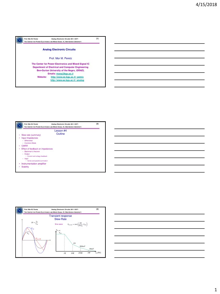
Transient response Slew-Rate

𝑊

𝑛_𝑝𝑣𝑢 = 𝑛𝑗𝑜

𝑇𝑆 2𝜌𝑔

𝑛

, 𝑊

𝑡𝑏𝑢

Vin Vout Vout_SR

𝑇𝑆 = 𝑗𝐶 𝐷𝑓𝑟 Sine wave

Vm_out Vsat 8V 800mV 1K 10K 100K 1M 80mV fm [Hz]

slide-2
SLIDE 2

4/15/2018 2

  • Prof. Mor M. Peretz

Analog Electronic Circuits 361-1-3671 THE CENTER FOR POWER ELECTRONICS AND MIXED-SIGNAL IC, BEN-GURION UNIVERSITY [4]

PE M I C

BGU

Input Impedances

Rcm

+

  • VOUT

Rd Rcm 𝑊

𝑑𝑛 = 𝑊 1 + 𝑊 2

2 𝑊

𝑒 = 𝑊 1 − 𝑊 2

Vcm Vd/2

+ + +

Vd/2 V1 V2

  • Prof. Mor M. Peretz

Analog Electronic Circuits 361-1-3671 THE CENTER FOR POWER ELECTRONICS AND MIXED-SIGNAL IC, BEN-GURION UNIVERSITY [5]

PE M I C

BGU

Input Impedances Differential

ℎ𝑗𝑓 = 𝑊𝑈 𝐽𝑓 ℎ𝑔𝑓 + 1 𝑆𝑒=2ℎ𝑗𝑓 = 2

𝑊𝑈 𝐽𝑓

ℎ𝑔𝑓 + 1

Q1 VEE Q2 VCC OUT IN- IN+ Rin

  • Prof. Mor M. Peretz

Analog Electronic Circuits 361-1-3671 THE CENTER FOR POWER ELECTRONICS AND MIXED-SIGNAL IC, BEN-GURION UNIVERSITY [6]

PE M I C

BGU

Input Impedances Common-mode

𝑆𝑓 = 1 ℎ𝑝𝑓 𝑆𝑑𝑛=2𝑆𝑓 ℎ𝑔𝑓 + 1

Q1 VEE Q2 VCC OUT IN- IN+ Rin

VEE

slide-3
SLIDE 3

4/15/2018 3

  • Prof. Mor M. Peretz

Analog Electronic Circuits 361-1-3671 THE CENTER FOR POWER ELECTRONICS AND MIXED-SIGNAL IC, BEN-GURION UNIVERSITY [7]

PE M I C

BGU

Common-Mode Rejection Ratio (CMRR)

𝐷𝑁𝑆𝑆 ≡ 𝐵𝑒 𝐵𝑑𝑛 = 𝐵𝑒𝐵2𝐵3 𝐵𝑑𝑛𝐵2𝐵3

+

  • Vin

VOUT R2 R1 V1 V2

  • +

Vin VOUT R2 R1 V1 V2 𝑊

𝑑𝑛 = 𝑊 1 + 𝑊 2

2 𝑊

𝑒 = 𝑊 1 − 𝑊 2

𝑊

𝑑𝑛 = 0

𝑊

𝑑𝑛 = 𝑊 𝑗𝑜

𝑊

𝑝𝑣𝑢_𝑑𝑛 = 𝐵𝑑𝑛𝑊 𝑑𝑛 = 𝐵𝑑𝑛

𝑊

1 + 𝑊 2

2

  • Prof. Mor M. Peretz

Analog Electronic Circuits 361-1-3671 THE CENTER FOR POWER ELECTRONICS AND MIXED-SIGNAL IC, BEN-GURION UNIVERSITY [8]

PE M I C

BGU

Common-Mode Rejection Ratio (CMRR)

+

  • Vin

VOUT R2 R1 V1 V2

  • +

Vin VOUT R2 R1 V1 V2 𝑊

𝑑𝑛 = 0

𝑊

𝑑𝑛 = 𝑊 𝑗𝑜

𝑊

𝑝𝑣𝑢=𝐵𝑑𝑛𝑊 𝑑𝑛+𝐵𝑒𝑊 𝑒 𝑊

𝑝𝑣𝑢

𝐵𝑒 = 𝑊

𝑑𝑛

𝐷𝑁𝑆𝑆 + 𝑊 𝑒 Reflected to input (as done to ALL non-idealities)

  • Prof. Mor M. Peretz

Analog Electronic Circuits 361-1-3671 THE CENTER FOR POWER ELECTRONICS AND MIXED-SIGNAL IC, BEN-GURION UNIVERSITY [9]

PE M I C

BGU

Blackman’s Theorem

𝑎𝐺=𝑎𝑂𝐺

1+𝛾𝐵𝑇𝐷 1+𝛾𝐵𝑃𝐷 +-

G AOL β Vin V’in Ve Vout Vf

Load

+-

G AOL β Vin V’in Ve Vf

Load

Iout

𝑎𝐺=

𝑎𝑂𝐺 1+𝛾𝐵

𝑎𝐺=𝑎𝑂𝐺 1 + 𝛾𝐵

Voltage feedback Current feedback

slide-4
SLIDE 4

4/15/2018 4

  • Prof. Mor M. Peretz

Analog Electronic Circuits 361-1-3671 THE CENTER FOR POWER ELECTRONICS AND MIXED-SIGNAL IC, BEN-GURION UNIVERSITY [10]

PE M I C

BGU

Effect of feedback Output impedance

  • +

Vin VOUT R2 R1 V1 V2 Voltage feedback

  • +

Vref R Iout

Current feedback

𝑎𝑝𝑣𝑢_𝐺=𝑆0

1+𝛾𝐵𝑇𝐷 1+𝛾𝐵𝑃𝐷

𝑎𝑝𝑣𝑢_𝐺=𝑆0

1+𝛾𝐵𝑇𝐷 1+𝛾𝐵𝑃𝐷

  • Prof. Mor M. Peretz

Analog Electronic Circuits 361-1-3671 THE CENTER FOR POWER ELECTRONICS AND MIXED-SIGNAL IC, BEN-GURION UNIVERSITY [11]

PE M I C

BGU

Effect of feedback Example

R1=10k R2=1k R0=100

  • +

Vin VOUT R2 R1 V1 V2

AOL [dB] f [Hz] 100 1/β R0 20 Zout_F 40

  • 40
  • Prof. Mor M. Peretz

Analog Electronic Circuits 361-1-3671 THE CENTER FOR POWER ELECTRONICS AND MIXED-SIGNAL IC, BEN-GURION UNIVERSITY [12]

PE M I C

BGU

Linear regulator Low-Drop Out (LDO)

+

Vout Zout_F ZLoad

slide-5
SLIDE 5

4/15/2018 5

  • Prof. Mor M. Peretz

Analog Electronic Circuits 361-1-3671 THE CENTER FOR POWER ELECTRONICS AND MIXED-SIGNAL IC, BEN-GURION UNIVERSITY [13]

PE M I C

BGU

Effect of feedback Input impedance

𝑎𝑗𝑜_𝐺=

𝑎𝑂𝐺 1+𝛾𝐵

𝑎𝑗𝑜_𝐺=𝑎𝑂𝐺 1 + 𝛾𝐵

Series (voltage) summation Parallel (current) summation

  • +

Vin VOUT R2 R1 Ve A Vf

β +

  • Vin

VOUT R2 R1 Ve

  • Prof. Mor M. Peretz

Analog Electronic Circuits 361-1-3671 THE CENTER FOR POWER ELECTRONICS AND MIXED-SIGNAL IC, BEN-GURION UNIVERSITY [14]

PE M I C

BGU

Input Impedances

+

  • Vin

VOUT R2 R1 V1 V2

  • +

Vin VOUT R2 R1 V1 V2

𝑆𝑗𝑜_1=𝑆2 𝑆𝑗𝑜_2=𝑆3+𝑆4 𝑆𝑗𝑜_1,2=𝑆2+𝑆3 𝑆𝑗𝑜=𝑆𝑒 1 + 𝛾𝐵 +

  • V1

VOUT R2 R1 VƐ V2 R3 R4

𝑆𝑗𝑜=𝑆2 +

𝑆1+𝑠0 1+𝛾𝐵 ≈ 𝑆2

  • Prof. Mor M. Peretz

Analog Electronic Circuits 361-1-3671 THE CENTER FOR POWER ELECTRONICS AND MIXED-SIGNAL IC, BEN-GURION UNIVERSITY [15]

PE M I C

BGU

Difference Amplifier

+

  • V1

VOUT R2 R1 VƐ V2 R3 R4 𝑊

𝑝𝑣𝑢_1 = −𝑊 1

𝑆1 𝑆2 𝑊

𝑝𝑣𝑢_2 = 𝑊 2

𝑆4 𝑆3 + 𝑆4 1 + 𝑆1 𝑆2

𝑆2 𝑆1 = 𝑆3 𝑆4

𝑊

𝑝𝑣𝑢 = 𝑆1

𝑆2 𝑊

2 − 𝑊 1

+

  • +
  • V1

VOUT R2 R1 VƐ V2 R3 R4

+

slide-6
SLIDE 6

4/15/2018 6

  • Prof. Mor M. Peretz

Analog Electronic Circuits 361-1-3671 THE CENTER FOR POWER ELECTRONICS AND MIXED-SIGNAL IC, BEN-GURION UNIVERSITY [16]

PE M I C

BGU

Instrumentation Amplifier

𝑊

𝑝𝑣𝑢 = 𝑆1

𝑆2 𝑊

𝑏𝑛𝑞_𝑐 − 𝑊 𝑏𝑛𝑞_𝑏

Vamp_a

+

  • VOUT

R2 R1 VƐ R3 R4

+

  • V1

Ra

+

  • V2

Rb Rx Vamp_b 𝐽𝑦 = 𝑊

1 − 𝑊 2

𝑆𝑦 𝑊

𝑏𝑛𝑞_𝑐 − 𝑊 𝑏𝑛𝑞_𝑏=𝐽𝑦 𝑆𝑦 + 𝑆𝑏 + 𝑆𝑐

𝑊

𝑝𝑣𝑢 = 𝑆1

𝑆2 𝑊

2 − 𝑊 1

1 + 𝑆𝑏 + 𝑆𝑐 𝑆𝑦

  • Prof. Mor M. Peretz

Analog Electronic Circuits 361-1-3671 THE CENTER FOR POWER ELECTRONICS AND MIXED-SIGNAL IC, BEN-GURION UNIVERSITY [17]

PE M I C

BGU

  • The system is unstable if the characteristic equation {1+βAOL(s)} has roots in

the right half of the complex plane

  • Nyquist criterion is a test for location of {1+βAOL(s)} roots
  • Nyquist criterion can be viewed on the frequency domain (Bode)

Loop-Gain Nyquist Criterion

𝐵𝐷𝑀 = 𝐻 𝑡 𝐵𝑃𝑀 𝑡 1 + 𝛾𝐵𝑃𝑀 𝑡

  • Prof. Mor M. Peretz

Analog Electronic Circuits 361-1-3671 THE CENTER FOR POWER ELECTRONICS AND MIXED-SIGNAL IC, BEN-GURION UNIVERSITY [18]

PE M I C

BGU

Loop-gain on the frequency domain

f f

 [dB] +180 |LG|

   

f A f  In negative feedback systems At f0 ) 180 ( 180

  +-

G AOL β Xin X’in Xe Xout Xf

slide-7
SLIDE 7

4/15/2018 7

  • Prof. Mor M. Peretz

Analog Electronic Circuits 361-1-3671 THE CENTER FOR POWER ELECTRONICS AND MIXED-SIGNAL IC, BEN-GURION UNIVERSITY [19]

PE M I C

BGU

f f

 [dB]

  • 180

A 

m

 1 A  

  • 1

| A |

  • 1

| A | m

180 ) 180 (        

   

Bode plot Phase margin

  • Prof. Mor M. Peretz

Analog Electronic Circuits 361-1-3671 THE CENTER FOR POWER ELECTRONICS AND MIXED-SIGNAL IC, BEN-GURION UNIVERSITY [20]

PE M I C

BGU

Graphical representation of βAOL conventional method

 Tedious – need to re-plot BA  Analysis (not design) oriented  Requires iterations

A

] dB [ B

3

f

B

] dB [ A

2

f

1

f ] Hz [ f ] Hz [ f ] dB [ AB

AB

3

f

2

f

1

f ] Hz [ f

  • Prof. Mor M. Peretz

Analog Electronic Circuits 361-1-3671 THE CENTER FOR POWER ELECTRONICS AND MIXED-SIGNAL IC, BEN-GURION UNIVERSITY [21]

PE M I C

BGU

] dB [ A ] Hz [ fo

A 1  BA BA

1 BA  1 BA  BA ) f ( LG  B 1

Graphical Representation of βAOL

20log(BA) B 1 20log A 20log   1 A B B 1 20log 20logA    

slide-8
SLIDE 8

4/15/2018 8

  • Prof. Mor M. Peretz

Analog Electronic Circuits 361-1-3671 THE CENTER FOR POWER ELECTRONICS AND MIXED-SIGNAL IC, BEN-GURION UNIVERSITY [22]

PE M I C

BGU

Possible compensations Rate of Closure (ROC)

f |A|  1

  • m

90  

  • m

45  

  • m

90  

  • m

45  

  • m

90  

  • m

45   f

dec db dec db

20 

dec db

40 

dec db

60 

db

A

s s s s u u

db

B 1 dec db

20 

dec db dec db

20 

dec db

40 

  • Prof. Mor M. Peretz

Analog Electronic Circuits 361-1-3671 THE CENTER FOR POWER ELECTRONICS AND MIXED-SIGNAL IC, BEN-GURION UNIVERSITY [23]

PE M I C

BGU

Overshoot and Q in Closed Loop in Response to step in Sin

t f Overshoot Q Overshoot

m

  • 50

Excitation ACL

  • m

m m

50 for sin cos Q     

  • m

45 target Design  

  • Prof. Mor M. Peretz

Analog Electronic Circuits 361-1-3671 THE CENTER FOR POWER ELECTRONICS AND MIXED-SIGNAL IC, BEN-GURION UNIVERSITY [24]

PE M I C

BGU

slide-9
SLIDE 9

4/15/2018 9

  • Prof. Mor M. Peretz

Analog Electronic Circuits 361-1-3671 THE CENTER FOR POWER ELECTRONICS AND MIXED-SIGNAL IC, BEN-GURION UNIVERSITY [25]

PE M I C

BGU