
SLIDE 1
3D for the public viewers
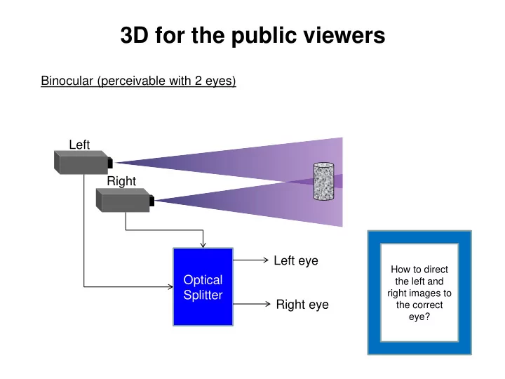
Binocular (perceivable with 2 eyes) Left Right Optical Splitter Left eye Right eye
How to direct the left and right images to the correct eye?
3D for the public viewers Binocular (perceivable with 2 eyes) Left - - PowerPoint PPT Presentation
3D for the public viewers Binocular (perceivable with 2 eyes) Left Right Left eye How to direct Optical the left and right images to Splitter Right eye the correct eye? Anaglyph Blue filter Red filter Transmission 475nm 650nm
Binocular (perceivable with 2 eyes) Left Right Optical Splitter Left eye Right eye
How to direct the left and right images to the correct eye?
Left picture Blue component only Right picture Red component only Projection
Transmission Wavelength 650nm 475nm 475nm Blue filter
Red filter Red filter Blue filter
Left picture polarized at 0 degree Right picture polarized at 90 degree 0 degree polarizer 90 degree polarizer
Usual approach: Display left and right eyes images on the same screen, and utilizes polarized glasses to direct each image to the corresponding eye.
. cos2
I = Malus’s law: Intensity is attenuated by the square of the cosine of the angle between the polarization directions of the light and the polarizing filter, as Hence, the viewing level must be strictly horizontal to avoid ghosting.
Projection
Circular Polarizing filter: polarization rotates clockwise or anticlockwise after passing through it.
Unpolarized light
http://upload.wikimedia.org/wikipedia/commons/d/d1/Circular.Polarization.Circularly.Polarized.Light_Left.H and.Animation.305x190.255Colors.gif
90o 0o
Anticlockwise polarizer Unpolarized light
90o 0o
Clockwise polarizer Polarizing angle
Circular Polarizing filter: polarization rotates clockwise or anticlockwise after passing through it.
Unpolarized light
90o 0o 90o 0o
Anticlockwise polarized light Anticlockwise polarizer Clockwise polarizer Block
Left picture Clockwise polarized Right picture Anticlockwise polarized Clockwise polarizer Anticlockwise polarizer
Using circular polarized images and glasses avoid the constraint on level
Projection
Time division multiplexing Left image Right image Left and right images are shown in the odd and even ( or even and odd) frames, respectively. L R L R L R Lower brightness as glasses are only conducted at 50% of time. Expensive and bulky active shutter glasses.
Synchronized to respective field Active shutter glass
Film-type Patterned Retarder: LG Checker sampling technology Left eye picture (cw-cp) Right eye picture (acw-cp) No flickering, brighter image. Low cost glasses. A film with circular polarizing element is placed on each pixel. Left and right pixels have different direction of polarization (cw- cp and acw-cp).
Picture resolution is lowered by a factor of 2.
Clockwise circular polarizer Anticlockwise circular polarizer
Origin: Classic lenticular 3D photographs. Basic concept: Interleave 2 or more views on the screen. Overlay a lenticular lens array, or a parallax barrier. The lens array or barrier deflects each view to its respective direction.
Left Eye Right Eye Interlaced image Lenticular lens array Left image pixel Right image pixel Interleaving and viewing of a pair of stereoscopic images
Interleaving left and right images on the screen can be described as a decimation and interpolation process.
Decimation, interpolation, and Interleaving of a pair of stereoscopic images
Decimation Interpolation A Decimation leads to distortion which cannot be fully recovered with interpolation.
Blank strip filled by the second image
Something is lost!
M is the decimation factor
r
=−
r
=−
i(n) is a periodic impulse train that can be expressed as
r j M nk k M
=− = −
2 1
r
=−
r j M nk k M
=− = −
2 1
j M nk k M j M nk k M
= − = −
2 1 2 1
j M nk k M j M nk k M
= − = −
2 1 2 1
According to equation (3)
nk k M
= −
2 1
j j k M k M
− = −
2 1
Converting the decimated signal y 𝑜 to frequency space with discrete Fourier transform:
𝑁 |0≤𝑙<𝑁.
𝑁, the replicas overlap with each other,
leading to aliasing error.
The frequency spectrum of x 𝑜 is 𝑌 𝑓𝑘𝜕 .
x(n) x’(n) y(n)
X e j ( )
−/4 /4 /2 /4 /4 /2 /4 /4 /2 /4 X e j '( )
−/4 /4 /2 /4 /4 /2 /4 /4 /2 /4 Y e j ( )
−/4 /4 /2 /4 /4 /2 /4 /4 /2 /4
M=4
e.g. M = 2
The frequency spectrum is scaled by a factor M. The frequency scale is compressed.
X e j ( )
−/4 /4 /2 /4 /4 /2 /4 /4 /2 /4
( )
Y e X e
j j M
( )
=
−/4 /4 /2 /4 /4 /2 /4 /4 /2 /4
M=4 No change other than a scaling of the frequency axis.
A pixel on the screen Intuitively, we can simply interleave the pixels on the monitor in alternating left and right manner.
Usual pixel arrangement
Early product by Sharp: Stereoscopic (2 views) with rainbow moiré pattern
Interleaving and viewing multi-view images Left pixel Right pixel
Slight difference in viewing positions capture incomplete pixel components
Avoiding rainbow moiré patterns: Rotate screen by 90 degree.
Left Eye Right Eye Interlaced images Lenticular lens array Interleaving and viewing multi-view images Left pixel Right pixel
Slight difference in viewing positions capture same pixel components. Very poor resolution for large number of views.
Rotated pixel arrangement
4 5 6 7 1 2 3 4 5 6 7 1 2 3 4 5 6 7 1 2 3 4 5 6 7 1 2 3 4 5 6 7 1 2 3 4 5 6 7 1 2 3 4 5 6 7 1 2 3 4 5 6 7 1 2 3 Lenticular lens array Magnified view of one lens column Very poor horizontal resolution
Rotating the lenticular lens array by certain degree
2 2 4 6 2 4 6 2 4 6 1 3 5 1 3 5 1 3 5 6 2 4 6 2 4 6 2 4 5 1 3 5 1 3 5 1 3 4 6 2 4 6 2 4 6 2 2 2 4 6 2 4 6 2 4 6 1 3 5 1 3 5 1 3 5 6 2 4 6 2 4 6 2 4 5 1 3 5 1 3 5 1 3 4 6 2 4 6 2 4 6 2 2 2 4 6 2 4 6 2 4 6 1 3 5 1 3 5 1 3 5 6 2 4 6 2 4 6 2 4 5 1 3 5 1 3 5 1 3 4 6 2 4 6 2 4 6 2
Philips patent: US6,064,424 (May 2000) Distribute resolution degradation to horizontal and vertical directions View 2 View 3 View 4
An early attempt to compress 3D stereoscopic sequences has been made by the MPEG with the incorporation of the Multiview Profile (MVP) [1][2] into the existing MPEG II standard. The approach is largely an extension of the temporal scalability, but so far the MVP has not been adopted as a commercially available service. [1] M. Tanimoto and T. Fuji, “Utilization of inter-view correlation for multiple view video coding”, ISO/IEC JTC1/SC29/WG11 M11014, July 2004. [2] H. Wang, et al, “Using inter-view prediction for multi-view video compression”, ISO/IEC JTC1/SC29/WG11 M10512, Mar. 2004.
Another approach has been developed by the Mitsubishi Electrical Research
views of video sequences with MPEG II and dispatches them via separate channel. At the receiver they were decoded and integrated and shown on the 3D
Broadcasting infrastructure. However the system is extremely complicated, requiring multiple PCs and high bandwidth networks on both the transmission and receiving sides.
The “Advanced Three-dimensional Television System Technologies (ATTEST) project [3] of the European Information Society Technologies (IST) aims at the development of a complete 3D-video chain including content creation, coding, transmission and display. “Depth Image Based Rendering” (DIBR) technology is adopted where a Three Dimensional Scene is encoded as a single view plus a depth map. To allow backward compatibility to existing 2D digital television, the base layer is encoded with MPEG II and DVB standards. The depth map is transmitted in the enhancement layer with MPEG 2/4/7 standard providing a depth value for each pixel in the base layer. At the receiver, 3D views are generated from the 2D image of the base layer and the depth map of the enhancement layer. [3] M.O. Beeck, “Towards an Optimized 3D Broadcast Chain”, Proc. SPIE 4864, Three-Dimensional TV, Video, and Display, 42 (November 1, 2002);
it is unlikely that the compressed multi-view 3D data could be distributed directly in the same way as the existing channels and standards. While it may be argued that technically, present standards and hardware solutions could always be changed to accommodate the newer technologies, such revolutions usually have to experience long period of incubation period before every components in the video chain could function collaboratively and survive in the consumer’s world.
StereoGraphics offers an alternative approach know as the “N-tiles”, a.k.a. the Hollywood Squares” format. Images from cameras each capturing a view of the scene are down-sampled and juxtaposed as non-overlapped tiles into a single picture. This enables multi-view images cav be processed in the same way as ordinary two dimensional pictures, and embedded into existing video chains.
In general, though not mandatory, the number of cameras N is taken to be the square of an integer D, i.e. W(n,x,y) is just an ordinary picture frame that can be modulated, compressed, broadcast and recorded by any existing standards.
N D =
At the receiving end, each view in W(n,x,y) is mapped to the corresponding sub-pixel in the auto-stereoscopic 3D monitor.