2019/5/6 Object-oriented Analysis and Design Object-oriented - - PDF document

2019 5 6
SMART_READER_LITE
LIVE PREVIEW

2019/5/6 Object-oriented Analysis and Design Object-oriented - - PDF document

2019/5/6 Object-oriented Analysis and Design Object-oriented Analysis and Design Chapters Iteration 1 basics 8. Applying UML and Patterns Domain models 9. 10. System sequence diagrams 11. Operation contracts An Introduction to 12.


slide-1
SLIDE 1

2019/5/6 1

Software Engineering

1 Object-oriented Analysis and Design

Applying UML and Patterns

An Introduction to Object-oriented Analysis and Design and Iterative Development

Part III Elaboration Iteration I – Basic1

Software Engineering

2 Object-oriented Analysis and Design

Chapters

8.

Iteration 1 – basics

9.

Domain models

  • 10. System sequence diagrams
  • 11. Operation contracts
  • 12. Requirements to design – iteratively
  • 13. Logical architecture and UML package diagrams
  • 14. On to object design
  • 15. UML interaction diagrams
  • 16. UML class diagrams
  • 17. GRASP: design objects with responsibilities
  • 18. Object design examples with GRASP
  • 19. Design for visibility
  • 20. Mapping design to code
  • 21. Test-driven development and refactoring

Software Engineering

3 Object-oriented Analysis and Design

Chap 10 System Sequence Diagrams

Software Engineering

4 Object-oriented Analysis and Design

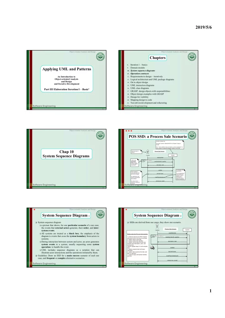
POS SSD: a Process Sale Scenario

enterItem(itemID, quantity) :System : Cashier endSale makePayment(amount) a UML loop interaction frame, with a boolean guard expression external actor to system Process Sale Scenario system as black box the name could be "NextGenPOS" but "System" keeps it simple the ":" and underline imply an instance, and are explained in a later chapter on sequence diagram notation in the UML a message with parameters it is an abstraction representing the system event of entering the payment data by some mechanism description, total return value(s) associated with the previous message an abstraction that ignores presentation and medium the return line is

  • ptional if nothing is

returned total with taxes change due, receipt makeNewSale [ more items ] loop

★ ★ ★

Software Engineering

5 Object-oriented Analysis and Design

System Sequence Diagram 1

 System sequence diagram  a picture that shows, for one particular scenario of a use case,

the events that external actors generate, their order, and inter- system events.

 All systems are treated as a black box; the emphasis of the

diagram is events that cross the system boundary from actors to systems.

 During interaction between system and actor, an actor generates

system events to a system, usually requesting some system

  • peration to handle the event.

 UML includes sequence diagrams as a notation that can

illustrate actor interactions and the operations initiated by them.

 Guideline: Draw an SSD for a main success scenario of each use

case, and frequent or complex alternative scenarios.

Software Engineering

6 Object-oriented Analysis and Design

System Sequence Diagram 2

 SSDs are derived from use cases; they show one scenario.

: Cashier :System Simple cash-only Process Sale scenario:

  • 1. Customer arrives at a POS checkout

with goods and/or services to purchase.

  • 2. Cashier starts a new sale.
  • 3. Cashier enters item identifier.
  • 4. System records sale line item and

presents item description, price, and running total. Cashier repeats steps 3-4 until indicates done.

  • 5. System presents total with taxes

calculated.

  • 6. Cashier tells Customer the total, and

asks for payment.

  • 7. Customer pays and System handles

payment. ... enterItem(itemID, quantity) endSale makePayment(amount) description, total total with taxes change due, receipt makeNewSale [ more items ] loop Process Sale Scenario

slide-2
SLIDE 2

2019/5/6 2

Software Engineering

7 Object-oriented Analysis and Design

System Sequence Diagram 3

 System events should be expressed at the abstract level of intention

rather than in terms of the physical input device.

 "enterItem" is better than "scan" (laser scan) because it captures the

abstract intent of the operation.

 design choices about what interface is used to capture the system

event (laser scanner, keyboard, voice input ..)

enterItem(itemID, quantity) scan(itemID, quantity) : Cashier worse name better name :System

Software Engineering

8 Object-oriented Analysis and Design

System Sequence Diagram 4

 Guideline

 show details of SSD in the Glossary.  The elements shown in SSDs (operation name, parameters, return

data) are terse.

 Iterative and Evolutionary SSDs - UP Phases

 Inception phase: SSDs are not usually motivated in inception, unless

you are doing rough estimating (don't expect inception estimating to be reliable) - function points or COCOMO II.

 Elaboration phase: Most SSDs are created during elaboration, when it

is useful to identify the details of the system events to clarify what major operations, write system operation contracts, and possibly to support estimation. Software Engineering

9 Object-oriented Analysis and Design

System Sequence Diagram - Buy-Item

Cashier

:System

System as block box Repeat until no more items

Buy-Item-version 1 Enteritem(UPC, quantity) endSale() makePayment(amount)

Actor System event It triggers a system operation Text which clarifies control, logic, iteration, etc. May be taken from the use case

Software Engineering

10 Object-oriented Analysis and Design

Chap 11 Operation Contracts

Software Engineering

11 Object-oriented Analysis and Design

POS Operation Contract

 Contract CO2: enterItem Operation: enterItem(itemID: ItemID, quantity: integer) Cross References: Use Cases: Process Sale Preconditions: There is a sale underway. Postconditions:

A

SalesLineItem instance sli was created (instance creation).

sli was associated with the current Sale (association

formed).

sli.quantity became quantity (attribute modification). sli was associated with a ProductDescription, based on

itemID match (association formed). Software Engineering

12 Object-oriented Analysis and Design

Sections of a Contract

 Operation: Name of operation, and parameters  Cross References: Use cases this operation can occur

within

 Preconditions: Noteworthy assumptions about the state

  • f the system or objects in the Domain Model before

execution of the operation.

 Postconditions: The state of objects in the Domain

Model after completion of the operation.

★ ★

slide-3
SLIDE 3

2019/5/6 3

Software Engineering

13 Object-oriented Analysis and Design

System Operations 1

 System operations  Define as Operation contracts  the system as a black box component offers in its public

interface.

 can be identified while sketching SSDs  SSDs show system events or I/O messages relative to the

system. Software Engineering

14 Object-oriented Analysis and Design

System Operations 2

: Cashier enterItem(itemID, quantity) endSale() makePayment(amount) description, total total with taxes change due, receipt makeNewSale() these input system events invoke system operations the system event enterItem invokes a system operation called enterItem and so forth this is the same as in object-

  • riented programming when

we say the message foo invokes the method (handling

  • peration) foo

[ more items ] loop :System Process Sale Scenario

 SSD. System operations handle input system events

Software Engineering

15 Object-oriented Analysis and Design

Postconditions 1

 Postconditions  describe changes in the state of objects in the domain model.  Domain

model state changes include instances created, associations formed or broken, and attributes changed.

 Postconditions are not actions to be performed.  Postconditions fall into these categories:  Instance creation and deletion.  Attribute change of value.  Associations (UML links) formed and broken.  Postconditions Related to the Domain Model  What instances can be created; What associations can be formed

in the Domain Model.

 Motivation: Why Postconditions?  Postconditions support fine-grained detail and precision in

declaring what the outcome of the operation must be.

★ ★ ★

Software Engineering

16 Object-oriented Analysis and Design

Postconditions 2

 Guideline: To Write a Postcondition  to emphasize state changes that arose from an operation, not an

action to happen.

 (better) A SalesLineItem was created.  (worse) Create a SalesLineItem, or, A SalesLineItem is created.  Analogy: The Spirit of Postconditions: The Stage and Curtain  The system and its objects are presented on a theatre stage.

 1.Before the operation, take a picture of the stage.  2.Close the curtains on the stage, and apply the system operation  3.Open the curtains and take a second picture.  4.Compare

the before and after pictures, and express as postconditions the changes in the state of the stage

 Guideline: How Complete Should Postconditions Be?  generating a complete and detailed set of postconditions for all

system operations is not likely or necessary. Software Engineering

17 Object-oriented Analysis and Design

Example: enterItem Postconditions

 Postconditions of the enterItem system operation.  Instance Creation and Deletion

 After the itemID and quantity of an item have been entered, what

new object should have been created? A SalesLineItem. Thus:

 A SalesLineItem instance sli was created (instance creation).

 Attribute Modification

 After the itemID and quantity of an item have been entered by the

cashier, what attributes of new or existing objects should have been modified? The quantity of the SalesLineItem should have become equal to the quantity parameter. Thus:

 sli.quantity became quantity (attribute modification).

 Associations Formed and Broken

 After the itemID and quantity of an item have been entered by the

cashier, what associations between new or existing objects should have been formed or broken?

 The new SalesLineItem should have been related to its Sale, and

related to its ProductDescription. Thus:

 sli was associated with the current Sale (association formed).  sli was associated with a ProductDescription, based on itemID match

(association formed). ★

Software Engineering

18 Object-oriented Analysis and Design

Guideline: Update the Domain Model

 It's common during the creation of the contracts to

discover the need to record new conceptual classes, attributes, or associations in the domain model.

 Enhance it as you make new discoveries while thinking

through operation contracts.

slide-4
SLIDE 4

2019/5/6 4

Software Engineering

19 Object-oriented Analysis and Design

Guideline: When Are Contracts Useful

 Consider an airline reservation system the system operation addNewReservation: the complexity

is very high regarding all the domain objects that must be changed, created, and associated.

These fine-grained details can be written up in the use

case, but it will make it extremely detailed (e.g., noting each attribute in all the objects that must change).

the postcondition offers and encourages a very precise,

analytical language.

 If developers can comfortably understand what to do

without them, then avoid writing contracts.

Software Engineering

20 Object-oriented Analysis and Design

Guideline: Create and Write Contracts

 Identify system operations from the SSDs.  For system operations that are complex and perhaps subtle in their results, or

which are not clear in the use case, construct a contract.

 To describe the postconditions, use the following categories:  instance creation and deletion  attribute modification  associations formed and broken  Writing Contracts  write the postconditions in a declarative, passive past form (was ..) to

emphasize the observation of a change rather than how it is going to be achieved.

 (better) A SalesLineItem was created.  (worse) Create a SalesLineItem.  To establish an association between existing objects or those newly created.  After the enterItem operation is complete, the newly created instance was

associated with Sale; thus:

 The SalesLineItem was associated with the Sale.  The most common problem is forgetting to include the forming of associations.

Particularly when new instances are created.

Software Engineering

21 Object-oriented Analysis and Design

Example: NextGen POS Contracts 1

 System Operations of the Process Sale Use Case  Contract CO1: makeNewSale  Operation:makeNewSale()  Cross References: Use Cases: Process Sale  Preconditions: none  Postconditions:

 A Sale instance s was created (instance creation).  s was associated with a Register (association formed).  Attributes of s were initialized.

 Keep it as light as possible, and avoid all artifacts unless they really add value.  Contract CO2: enterItem  Operation: enterItem(itemID: ItemID, quantity: integer)  Cross References: Use Cases: Process Sale  Preconditions: There is a sale underway.  Postconditions:

 A SalesLineItem instance sli was created (instance creation).  sli was associated with the current Sale (association formed).  sli.quantity became quantity (attribute modification).  sli was associated with a ProductDescription, based on itemID match

(association formed).

Software Engineering

22 Object-oriented Analysis and Design

Example: NextGen POS Contracts 2

 Contract CO3: endSale  Operation: endSale()  Cross References: Use Cases: Process Sale  Preconditions: There is a sale underway.  Postconditions:

 Sale.isComplete became true (attribute modification).

 Contract CO4: makePayment  Operation: makePayment( amount: Money )  Cross References: Use Cases: Process Sale  Preconditions:There is a sale underway.  Postconditions:

 A Payment instance p was created (instance creation).  p.amountTendered became amount (attribute modification).  p was associated with the current Sale (association formed).  The current Sale was associated with the Store (association

formed); (to add it to the historical log of completed sales)

Software Engineering

23 Object-oriented Analysis and Design

Process: Operation Contracts Within the UP

 In the UML, operations exists at many levels, from

System down to fine-grained classes, such as Sale.

Operation contracts for the System level are part of the

Use-Case Model.

 Inception phase Contracts are not motivated during inception, they are too

detailed.

 Elaboration phase If used at all, most contracts will be written during

elaboration, when most use cases are written. Only write contracts for the most complex and subtle system

  • perations.