
SLIDE 1
1
ME 499-699 Fall 2006 Slides 9 -1
More info: “Materials Selection in Mechanical Design”, Chapters 11 and 12
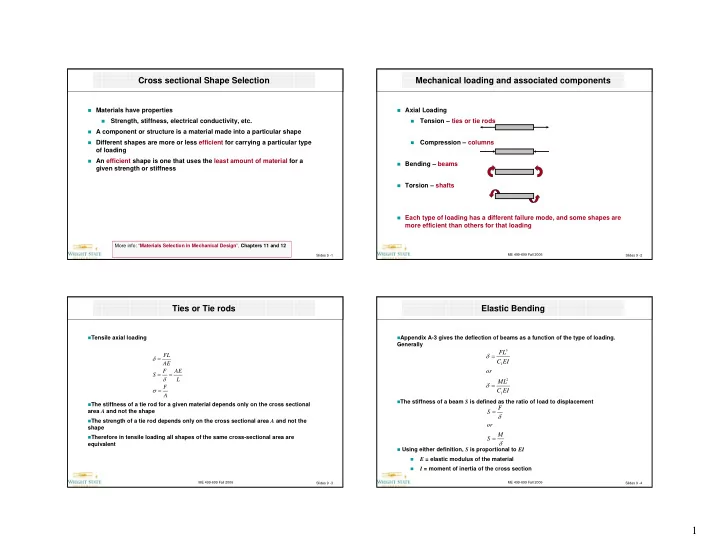
Cross sectional Shape Selection
Materials have properties
- Strength, stiffness, electrical conductivity, etc.
A component or structure is a material made into a particular shape Different shapes are more or less efficient for carrying a particular type
- f loading
An efficient shape is one that uses the least amount of material for a
given strength or stiffness
ME 499-699 Fall 2006 Slides 9 -2
Mechanical loading and associated components
Axial Loading
- Tension – ties or tie rods
- Compression – columns
Bending – beams Torsion – shafts Each type of loading has a different failure mode, and some shapes are
more efficient than others for that loading
ME 499-699 Fall 2006 Slides 9 -3
Ties or Tie rods
Tensile axial loading The stiffness of a tie rod for a given material depends only on the cross sectional
area A and not the shape
The strength of a tie rod depends only on the cross sectional area A and not the
shape
Therefore in tensile loading all shapes of the same cross-sectional area are
equivalent A F L AE F S AE FL = = = = σ δ δ
ME 499-699 Fall 2006 Slides 9 -4
Elastic Bending
Appendix A-3 gives the deflection of beams as a function of the type of loading.
Generally
The stiffness of a beam S is defined as the ratio of load to displacement Using either definition, S is proportional to EI
- E = elastic modulus of the material
- I = moment of inertia of the cross section
EI C ML
- r
EI C FL
1 2 1 3
= = δ δ δ δ M S
- r