1 HRTI-3 DEM Specification Requirement Specification Value - - PDF document

1
SMART_READER_LITE
LIVE PREVIEW

1 HRTI-3 DEM Specification Requirement Specification Value - - PDF document

TanDEM-X: Mission and Science Exploration Irena Hajnsek & Alberto Moreira TDX Science Team German Aerospace Center (DLR) Microwaves and Radar Institute Folie 1 irena.hajnsek@dlr.de - 25.01.2007 Primary Mission Goal The main goal of the


slide-1
SLIDE 1

1

Folie 1 irena.hajnsek@dlr.de

  • 25.01.2007

TanDEM-X: Mission and Science Exploration

Irena Hajnsek & Alberto Moreira TDX Science Team

German Aerospace Center (DLR) Microwaves and Radar Institute

Folie 2 Microwaves and Radar Institute

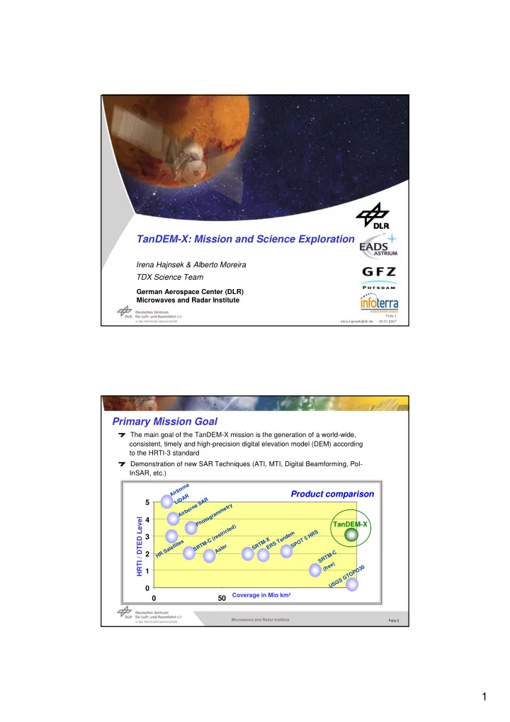
The main goal of the TanDEM-X mission is the generation of a world-wide, consistent, timely and high-precision digital elevation model (DEM) according to the HRTI-3 standard Demonstration of new SAR Techniques (ATI, MTI, Digital Beamforming, Pol- InSAR, etc.)

1 2 3 4 5 50

Coverage in Mio km²

Airborne LIDAR Airborne SAR Photogrammetry SRTM-C (restricted) HR Satellites Aster SRTM-C (free) SRTM-X

TanDEM-X

ERS Tandem SPOT 5 HRS

Product comparison

HRTI / DTED Level

USGS GTOPO30

Primary Mission Goal

slide-2
SLIDE 2

2

Folie 3 Microwaves and Radar Institute

HRTI-3 DEM Specification

0.4 arcsec (~ 12 m) fixed latitude/longitude raster Horizontal Post Spacing 2 m 90 % point-to-point errors Relative Vertical Accuracy 10 m 90 % single point error Absolute Vertical Accuracy 10 m 90 % circular error Horizontal Accuracy Value Specification Requirement

absolute height error single point errors

(90% confidence interval)

point-to-point errors

(90% confidence interval) h Δ h Δ ⋅ 2 ~ h Δ

relative height error Definition of 90% point-to-point errors: 1° 1°

h HRTI

h σ ⋅ ≈ Δ 33 . 2

% 90

Folie 4 Microwaves and Radar Institute

TanDEM-X Radar Techniques and Application Areas

Digital Elevation Model (DEM) Radar Data Product (RDP) TanDEM-X Application

Across-track Along-track New Techniques Land Cover & Vegetation Land Environment Glaciology/Hydrology Geology Oceanography Traffic Oceanography Hydrology/Glaciology Bistatic Processing Pol-InSAR Digital Beamforming Super Resolution Formation Flying InSAR Processing

slide-3
SLIDE 3

3

Folie 5 Microwaves and Radar Institute

Radar Data Products

  • Standard DEMs
  • Δh = 2m @ 12m posting (HRTI-3)
  • also: 1m @ 25m and 0.5m @ 50m

4m @ 6m (on special request)

  • global access
  • Customised DEMs
  • improved resolution

(e.g. 1m @ 6m ~ HRTI-4)

  • multiple DEMs (different seasons/years)
  • only on local/regional basis
  • Supporting information
  • geocoded SAR images
  • coherence maps
  • height error maps
  • TanDEM-X provides data for
  • along-track interferometry
  • polarimetric SAR interferometry
  • four phase centre MTI
  • digital beamforming, …
  • Policy
  • user is responsible for higher level

data production

  • supporting analysis by DLR
  • Deliverables
  • SLC SAR images
  • auxiliary data (baselines, …)
  • interferograms (if applicable)
  • SAR raw data (on special request)

DEM Products TanDEM-X Product Classes

Folie 6 Microwaves and Radar Institute

Scientific User Requirements Survey

JUSTIFICATION & NEEDS TECHNICAL REQUIREMENTS PRODUCT DEFINITION CONSOLIDATED SCIENTIFIC REQUIREMENTS Science Response

1. Justification and Needs: General frame (application area, needs, National/European/International relevance, justification) 2. Technical Requirements: Quantitative display (performance, operation, product) 3. Product Acceptance: Defined Products (defined and being confirmed by the science team)

slide-4
SLIDE 4

4

Folie 7 Microwaves and Radar Institute

Capabilities of TanDEM-X

TanDEM-X is a highly flexible sensor which enables multiple powerful imaging modes

  • 4 Phase Center MTI (traffic, …)
  • PolInSAR (vegetation height, …)
  • Digital Beamforming (HRWS)
  • Bistatic Imaging (classification, ..)
  • Large Scale Velocity Fields

(ocean currents, glacier flow, …)

  • Moving Object Detection
  • Temporal Coherence Maps
  • Digital Elevation Models
  • Spatial Coherence (forest, …)
  • Double DInSAR (change maps, ..)
  • High Resolution Radar Maps

New Techniques Along-Track Interferometry Cross-Track Interferometry

r+Δr r

t+Δt t interferometric modes (bistatic, alternating, monostatic) SAR modes (ScanSAR, Stripmap, …) cross-track baselines (0 km to several km) along-track baselines (0 km to several 100 km) polarisations (single, dual, quad) … bandwidth / resolution (0 ... 150/300 MHz) incident angles (20° ... 55°)

Folie 8 Microwaves and Radar Institute

slide-5
SLIDE 5

5

Folie 9 Microwaves and Radar Institute

Across-Track Interferometry

Topography Navigation Urban areas Crisis management Glaciology Oceanography Geology Hydrology Land cover

Scientific Applications

Folie 10 Microwaves and Radar Institute

Along-Track Interferometry & New Techniques

Rx

θ

Tx

θ φ

Rx

θ

Tx

θ φ

Receiver Transmitter Receiver Transmitter

64 km/h 56 km/h 68 km/h

Ocean Currents Traffic Monitoring Glacier Mass Balance Bi-Static SAR Polarimetric InSAR Digital Beamforming InSAR Processing Super Resolution Formation Flying

slide-6
SLIDE 6

6

Folie 11 Microwaves and Radar Institute

Single Pass X-Band InSAR Application Examples for TanDEM-X

Svalex campaign 2005 over the Austfonna glacier Topography measurements Urban area campaign 2005 campaign over Munich Coherent scatterer detection (single and quad pol) Boreal forest mapping campaign in Finland Boreal forest heights estimation and comparison 2D ocean velocity measurements First simulation results Across-track Along-track New Techniques New Techniques

+

Folie 12 Microwaves and Radar Institute

Cooperation between two Institutions:

  • 1. DLR-HR (Microwaves and Radar Institute)

* Pol-InSAR measurements over land ice * penetration depth at different frequencies * retrieval of glacier topography * estimation of internal ice structures 2.AWI-Potsdam (Alfred-Wegner Institute) * measurements of optical, chemical, and physical properties of Arctic aerosols (Arctic Haze) 3.AWI-Bremerhaven (Alfred-Wegner Institute) * boundary layer meteorology * transfer of atmospheric momentum to sea ice * use of radar imagery to quantify ice ks

SVALEX 2005 – Svalbard Airborne Experiment

Sensors: 1. E-SAR Radar System 2. Meteopod (wind velocity, humidity, temp.) 3. Laser Altimeter 4. KT15 (surface temp.) 5. Linescan camera

slide-7
SLIDE 7

7

Folie 13 Microwaves and Radar Institute

Austfonna ETON (GlacierArea): Single InSAR X- band @VV

Amplitude VV (mean dB -8.32) InSAR Phase VV InSAR Coh. VV (mean coh: 0.82)

az rg

Folie 14 Microwaves and Radar Institute

Summit Area: X- band (VV) Penetration depth

4.5 Phase Difference [mean] 7.7 Penetration Depth [m] 0.82 InSAR Coherence X Band VV Frequency/ Polarisation Amplitude InSAR Coh

slide-8
SLIDE 8

8

Folie 15 Microwaves and Radar Institute

Coherent Scatterers (CSs) Detected at X-band

Chirp bandwidth 100Mhz Range resolution 1.5m Azimuth resolution 0.63m

Near range

CSs are detected through spectral correlation in range direction Number of points detected ~ 95000 HH / X Band / Munich CS / HH / X Band / Munich

Folie 16 Microwaves and Radar Institute

PI-SAR X-band Test Site: Gifu, Japan Courtesy for the provision of X Band data: Hiroshi Kimura

Detection of Coherent Points R: HH G: HV B: VV

Polarimetric SAR X Band for CS’s Detection

slide-9
SLIDE 9

9

Folie 17 Microwaves and Radar Institute

Test Site: Oberpfaffenhofen Amplitude Image – X-band Interferometric Phase – Baseline 1 Interferometric Phase – Baseline 2 Interferometric Coherence - Baseline 1 Interferometric Coherence - Baseline 2

X Band Single-Pass Dual Baseline Interferometry

Folie 18 Microwaves and Radar Institute

E-SAR / Test Site: Oberpfaffenhofen Amplitude Image – X-band Interferometric Coherence - Baseline 1 Interferometric Coherence - Baseline 2

X Band Single-Pass Dual Baseline Interferometry

slide-10
SLIDE 10

10

Folie 19 Microwaves and Radar Institute

E-SAR / Test Site: Helsinki, Finland Forest Height estimated at X-band & HUTSCAT Height Profiles

X Band Single-Pass Interferometry

Boreal forest height inversion

Folie 20 Microwaves and Radar Institute

2-D Current Measurements with TanDEM-X

Squinted Split Antenna Mode

Ocean Eddie Simulated Tandem-X Measurement Proposal by IMF to use Tandem-X in a squinted split antenna mode configuration for 2-D current measurements

Courtesy: IMF Johannes Schulz-Stellenfleth

slide-11
SLIDE 11

11

Folie 21 Microwaves and Radar Institute

Summary: Science Exploitation

TanDEM-X will provide novel DEM quality fully compliant to a variety

  • f different scientific applications with global access.

TanDEM-X will demonstrate new SAR techniques in space for the development of future SAR systems. TanDEM-X will deliver two main categories of products (DEM & RDP) TanDEM-X mission is an evolution capitalizing on technology and experience from SRTM and TerraSAR-X.

Science TanDEM-X is a unique system accounting for scientific (ongoing development), technical (experimental) and commercial (operational) demands.

Folie 22 Microwaves and Radar Institute

Next X-band Satellite Mission