
SLIDE 1
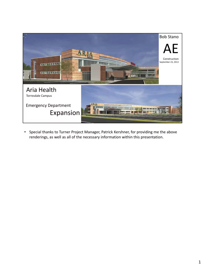
- Special thanks to Turner Project Manager, Patrick Kershner, for providing me the above
1 Primary Reasoning: Aria Health systems is the largest healthcare - - PDF document
Special thanks to Turner Project Manager, Patrick Kershner, for providing me the above renderings, as well as all of the necessary information within this presentation. 1 Primary Reasoning: Aria Health systems is the largest healthcare