1 Mor M. Peretz, Switch-Mode Power Supplies [8-4] Control of PWM - - PDF document

1
SMART_READER_LITE
LIVE PREVIEW

1 Mor M. Peretz, Switch-Mode Power Supplies [8-4] Control of PWM - - PDF document

Mor M. Peretz, Switch-Mode Power Supplies [8-1] Control of switch-mode converters Mor M. Peretz, Switch-Mode Power Supplies [8-2] Control objectives Produce control command to Regulate the output voltage Obtain zero or small


slide-1
SLIDE 1

1

Mor M. Peretz, Switch-Mode Power Supplies

[8-1]

Control of switch-mode converters

Mor M. Peretz, Switch-Mode Power Supplies

[8-2]

Control objectives

Produce control command to

  • Regulate the output voltage
  • Obtain zero or small steady-state (DC) error
  • Quick response to reference changes
  • Fast recovery
  • Immunity to input and load changes
  • Reasonable overshoot

Mor M. Peretz, Switch-Mode Power Supplies

[8-3]

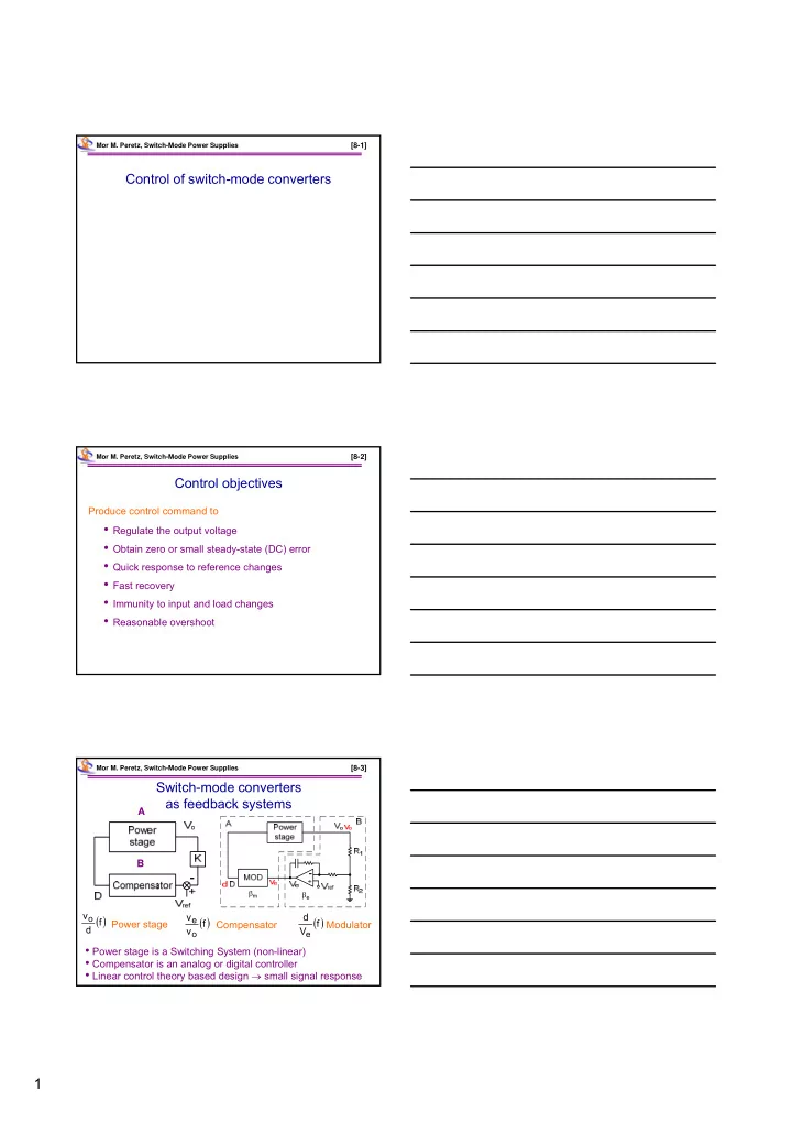
Switch-mode converters as feedback systems

m

e

  • Power stage is a Switching System (non-linear)
  • Compensator is an analog or digital controller
  • Linear control theory based design  small signal response

A B

 

f v v

  • e

Compensator

 

f d vo Power stage

 

f V d

e

Modulator

slide-2
SLIDE 2

2

Mor M. Peretz, Switch-Mode Power Supplies

[8-4]

Control of PWM converters disturbances in voltage mode

Mor M. Peretz, Switch-Mode Power Supplies

[8-5]

Voltage regulation

( power ) Duty cycle Feedback ( power ) Power stage Vin VO RO CO

Driver k error amp VO PWM modulator Ve Vref

Mor M. Peretz, Switch-Mode Power Supplies

[8-6]

PWM modulator

Ve +

  • Vv

comp Vp Ve  

p v t v s

V V t V V T   

 

p v

  • n

t e v s

V V t V V V T      

e v

  • n
  • n

s p v

V V t D T V V    

Practical Don max  0.8  0.9

D 1 Vv Vp Ve

Oscillator

slide-3
SLIDE 3

3

Mor M. Peretz, Switch-Mode Power Supplies

[8-7]

Sawtooth generator

Mor M. Peretz, Switch-Mode Power Supplies

[8-8]

Transfer functions

m

e

t t Zoom Ve D t d D

Mor M. Peretz, Switch-Mode Power Supplies

[8-9]

Control of PWM converters disturbances in voltage mode

  • ut
  • ut

vin in d

  • ut

Z i A v dA v   

  • ut

i in v

  • ut

d

d v A

 

  • ut

i d in

  • ut

vin

v v A

 

d in v

  • ut
  • ut
  • ut

i v Z

 

LG 1 Z i LG 1 A v LG 1 LG K 1 v v

  • ut
  • ut

vin in t ref

  • ut

     

d M t

BA K K LG 

slide-4
SLIDE 4

4

Mor M. Peretz, Switch-Mode Power Supplies

[8-10]

Dynamics of feedback systems

Block diagram division B A ) f ( LG 

A – known (power stage + divider) B – unknown (have to be designed)

 S

in

S

f

S

+

  • ut

S

K

P

1

H

A

B

Mor M. Peretz, Switch-Mode Power Supplies

[8-11]

) s ( LG 1 ) s ( A ACL  

  • The system is unstable if {1+LG(s)} has roots in the

right half of the complex plane.

  • Nyquist criterion is a test for location of {1+LG(s)}

roots.

  • Nyquist criterion is normally translated into the Bode

plane (frequency domain)

LoopGain test

Nyquist Criterion

Mor M. Peretz, Switch-Mode Power Supplies

[8-12]

LoopGain test

f f

 db +180 |LG|

   

f A f  In negative feedback systems At f0 ) 180 ( 180

 

slide-5
SLIDE 5

5

Mor M. Peretz, Switch-Mode Power Supplies

[8-13]

f f

 db

  • 180

A 

m

 180o already substracted 1 A  

  • 1

| A |

  • 1

| A | m

180 ) 180 (        

   

Bode plot

Mor M. Peretz, Switch-Mode Power Supplies

[8-14]

Graphical representation of BA conventional method

 Tedious – need to re-plot BA  Analysis (not design) oriented  Requires iterations

A

] dB [ B

3

f

B

] dB [ A

2

f

1

f ] Hz [ f ] Hz [ f ] dB [ AB

AB

3

f

2

f

1

f ] Hz [ f

Mor M. Peretz, Switch-Mode Power Supplies

[8-15]

] dB [ A ] Hz [ fo

A

1  B A

1 BA  1 BA  BA ) f ( LG  B 1

Graphical Representation of BA

20log(BA) B 1 20log A 20log   1 A B B 1 20log 20logA    

slide-6
SLIDE 6

6

Mor M. Peretz, Switch-Mode Power Supplies

[8-16]

Possible compensations

 

dB d Vo dec dB 40

  • dec

dB 20

  • Mor M. Peretz, Switch-Mode Power Supplies

[8-17]

Possible compensations

 1

  • m

90  

  • m

45  

  • m

90  

  • m

45  

  • m

90  

  • m

45  

f

dec db dec db

20 

dec db

40 

dec db

60 

db

A

s s s s u u

db

B 1

dec db

20 

dec db dec db

20 

dec db

40 

Mor M. Peretz, Switch-Mode Power Supplies

[8-18]

Overshoot and Q in Closed Loop in Response to step in Sin

t f Overshoot Q Overshoot

m

  • 50

Excitation ACL

  • m

m m

50 for sin cos Q     

  • m

45 target Design  

slide-7
SLIDE 7

7

Mor M. Peretz, Switch-Mode Power Supplies

[8-19]

Extracting the power stage control-to-output transfer function

L

  • C
  • R

in

V

  • V

L

I

in

E

b

G S L

  • C
  • R

in

V D

  • V

in

  • L

E V V  

in in

  • n

E V D  

b

  • n

L

G I D  

Mor M. Peretz, Switch-Mode Power Supplies

[8-20]

Linearization

R V(in) I(3)

  • ut

( ) ( ) (3) V out V in I  

( ( )) ( ( )) ( ( )) ( ) (3) ( ( )) ( (3)) V out V out d V out v in i V in I       ( ) ( ) ( ) ( ) (3) ( ) (3) V out V out V out v in i V in I      

Mor M. Peretz, Switch-Mode Power Supplies

[8-21]

SPICE Linearization (AC Analysis)

(3) ( ) F I V in   

R V(in) I(3)

  • ut

R

  • ut

) 3 ( i ) 3 ( I F

       

) in ( V ) in ( V F

       

( ) (3) F V in I   

slide-8
SLIDE 8

8

Mor M. Peretz, Switch-Mode Power Supplies

[8-22]

Buck linearization

L

  • C
  • ut

in

V

L

I

b

G

in

E

in

  • R

D I G

L b 

D V E

in in 

  • ut
  • in

D E        

  • in

in

V E         L Vin ) in ( v ) d ( V

0 

) d ( v ) in ( V

0 

in

  • b

D G        

  • L

b

I G         ) d ( v ) L ( I

0 

) L ( i ) d ( V

0  L

I Co Ro

D

V VAC d R Mor M. Peretz, Switch-Mode Power Supplies [8-23] f f p

R C 2 1 f  

in f

  • R

R A 

Possible phase compensation schemes Lag network

Mor M. Peretz, Switch-Mode Power Supplies

[8-24]

Design example

slide-9
SLIDE 9

9

Mor M. Peretz, Switch-Mode Power Supplies

[8-25]

Lag network

Frequency 100Hz 10KHz 1.0MHz 10Hz p(-V(out1))

  • 100d
  • 50d

0d SEL>> db(V(out1))

  • 40

40 E1 V(%IN+, %IN-)*1E6 EVALUE OUT+ OUT- IN+ IN- R1 1k 0V C1 10n R2 100k V1 1Vac 0Vdc 0V 0V

  • ut1

Mor M. Peretz, Switch-Mode Power Supplies

[8-26]

2

( .) 1 2

  • OL

L f f f in

A A ampl f C R R A R    

f  1 f

dec db

20  f1 f2 A0 A2

Lag – Lead network

Mor M. Peretz, Switch-Mode Power Supplies

[8-27]

Lag-Lead network

Frequency 100Hz 10KHz 1.0MHz 10Hz p(-V(out2))

  • 100d
  • 50d

0d SEL>> db(V(out2)) 50 100 E3 V(%IN+, %IN-)*1E6 EVALUE OUT+ OUT- IN+ IN- C2 10n R9 1g 0V

  • ut2

0V R3 10k 0V R4 1k V2 1Vac 0Vdc

slide-10
SLIDE 10

10

Mor M. Peretz, Switch-Mode Power Supplies

[8-28]

Double zero compensation scheme

2 1 3 2

R R C C  

β β 1

dec dB 20                                         

3 3 1 1 1 2 2 3

C R 1 C R 1 C R 1 C R 1        π π π π 2 2 2 2

3 2C

R f 2 1  π OL

A

2 3

R R

3 2C

R f 2 1  π

1 3

R R Mor M. Peretz, Switch-Mode Power Supplies [8-29]

Double Zero

Frequency 100Hz 10KHz 1.0MHz 10Hz p(-V(out3))

  • 100d

0d 100d SEL>> db(V(out3)) 20 40 C5 10n C3 10n 0V R7 100k V3 1Vac 0Vdc 0V R8 1g

  • ut3

R5 1k E2 V(%IN+, %IN-)*1E6 EVALUE OUT+ OUT- IN+ IN- R6 100k C4 100p 0V

Mor M. Peretz, Switch-Mode Power Supplies

[8-30]

The relationship to PID compensators

 

dB V V e c

1

f

2

f

   

s ω s ω s K K K s s K K v v

z2 z1 I d d I p e c

       

 

dB V V e c

1

f

2

f

slide-11
SLIDE 11

11

Mor M. Peretz, Switch-Mode Power Supplies

[8-31]

The relationship to PID compensators

 

dB d Vo dec dB 40

  • dec

dB 20

  • Mor M. Peretz, Switch-Mode Power Supplies

[8-32]

Mor M. Peretz, Switch-Mode Power Supplies

[8-33]

slide-12
SLIDE 12

12

Mor M. Peretz, Switch-Mode Power Supplies

[5-34]