1 asynchronous and synchronous transmission
play

1. Asynchronous and Synchronous Transmission Synchronization: - PDF document

1 Chap. 5 Data Communication Interface 1. Asynchronous and Synchronous Transmission Synchronization: Sender & receiver need to synchronize Different levels of sync Clock sync: bit level Block sync: block or message


  1. 1 Chap. 5 Data Communication Interface 1. Asynchronous and Synchronous Transmission • Synchronization: – Sender & receiver need to synchronize – Different levels of sync • Clock sync: bit level • Block sync: block or message level (character/word level) • 
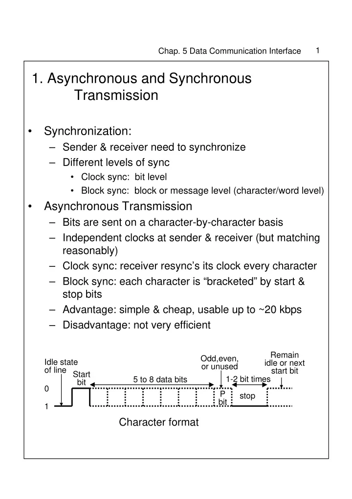
Asynchronous Transmission – Bits are sent on a character-by-character basis – Independent clocks at sender & receiver (but matching reasonably) – Clock sync: receiver resync’s its clock every character – Block sync: each character is “bracketed” by start & stop bits – Advantage: simple & cheap, usable up to ~20 kbps – Disadvantage: not very efficient Remain Odd,even, Idle state idle or next or unused of line Start start bit 5 to 8 data bits 1-2 bit times bit 0 P stop bit 1 Character format

  2. 2 Chap. 5 Data Communication Interface 0 100 200 300 400 500 600 700 800 start 0 93 186 279 372 465 558 651 744 Effect of timing error • Synchronous Transmission – Sender & receiver have identical clocks • Separate clock line to carry clock signal from sender • “Self-clocking” transmission scheme – Biphase encoding (e.g. Manchester) ← digital sig. – Using carrier signal ← Analog sig. • Block sync: – Special preamble & postamble bit patterns used to indicate start/end of a block (frame) 8-bit Control 8-bit Control Data field flag fields flag fields Synchronous frame format

  3. 3 Chap. 5 Data Communication Interface 2. Line Configurations • Topology – Physical arrangements of stations on a transmission medium – Point-to-point & Multipoint • Full Duplex and Half Duplex Send and receive Half-duplex A B Only one way at a time Send Full-Duplex A B receive simultaneously

  4. 4 Chap. 5 Data Communication Interface 3. Interfacing • Need a interface standard between DTE & DCE which specify in detail – mechanical – electrical – functional – procedural interface • An example of physical layer protocol

  5. 5 Chap. 5 Data Communication Interface • V.24/EIA-232-E – Interface standard between DTE and DCE – RS-232 was introduced in 1962 by EIA, and current version is EIA-232-E (5th version), and International version is ITU-T V.24 • RS: Recommended Standard • EIA: Electronics Industry Association • ITU: International Telecommunications Union (which has superseded CCITT) • ITU-T: ITU standard for Telecommunications – Originally for modem, but can be used with digital networks – Official title for the standard is “Interface between DTE and DCE employing serial binary data interchange” – Mechanical Specification • specifics of the connector, assignment of interchange circuits to pins, size, dimensions, etc. • 25-pin connector (known as D-connector) • since not all 25 pins are necessary, 9-pin D- connectors are also available

  6. 6 Chap. 5 Data Communication Interface Pin assignments – Electrical Specification • NRZ-L – Binary 1 (or OFF): -3V ~ -15V, – Binary 0 (or ON): +3V ~ +15V • For less than 20 kbps and 15 meters – Functional Specification • Functional specification of each interchange circuit, i.e., meaning of each circuit • Circuits can be grouped into the categories of data,control, timing, and ground

  7. 7 Chap. 5 Data Communication Interface for 9-pin connector

  8. 8 Chap. 5 Data Communication Interface – Loopback testing • Useful fault-isolating tool • Local loopback & remote loopbck Loopback circuit settings for V.24/EIA-232 Local loopback Remote loopback Local Remote Circuit Condition Circuit interface interface DCE ready ON DCE ready ON OFF Local loopback ON Local loopback OFF OFF Remote loopback OFF Remote loopback ON OFF Test mode ON Test mode ON ON

  9. 9 Chap. 5 Data Communication Interface – Procedural Specification • Legal sequence of events for a particular application • Example1: Asynchronous private line modem (limited-distance modem) – less than 2.5km apart DTE Transmitting Request Transmit DTE ready to send data to DCE time DTE DCE Clear DCE ready to send DTE Receiving Receive data time DTE DCE Receive data Set Received-line from channel signal detector and send to DTE over Received data • Example 2: Modem over the telephone network – Need additional circuit: ring indicator

  10. 10 Chap. 5 Data Communication Interface V.24/EIA-232 dial-up operation

  11. 11 Chap. 5 Data Communication Interface – Null Modems • Allow two DTEs communicate directly (with no networks nor DCEs between them) DTE DTE

Download Presentation
Download Policy: The content available on the website is offered to you 'AS IS' for your personal information and use only. It cannot be commercialized, licensed, or distributed on other websites without prior consent from the author. To download a presentation, simply click this link. If you encounter any difficulties during the download process, it's possible that the publisher has removed the file from their server.

Recommend


More recommend