1 Asynchronous - Behavior Synchronous - Bit Level In a steady - - PDF document

1
SMART_READER_LITE
LIVE PREVIEW

1 Asynchronous - Behavior Synchronous - Bit Level In a steady - - PDF document

Asynchronous and Synchronous Transmission Timing problems require a mechanism to synchronize the transmitter and receiver Two solutions Asynchronous Chapter 6 Synchronous Digital Data Communications Transmission Errors:


slide-1
SLIDE 1

1

Chapter 6 Digital Data Communications Techniques

Asynchronous and Synchronous Transmission

  • Timing problems require a mechanism to

synchronize the transmitter and receiver

  • Two solutions

—Asynchronous —Synchronous

  • Transmission Errors: Detection and Correction
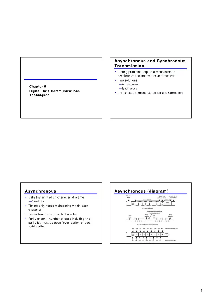
Asynchronous

  • Data transmitted on character at a time

—5 to 8 bits

  • Timing only needs maintaining within each

character

  • Resynchronize with each character
  • Parity check – number of ones including the

parity bit must be even (even parity) or odd (odd parity)

Asynchronous (diagram)

slide-2
SLIDE 2

2

Asynchronous - Behavior

  • In a steady stream, interval between characters

is uniform (length of stop element)

  • In idle state, receiver looks for transition 1 to 0
  • Then samples next seven intervals (char length)
  • Then looks for next 1 to 0 for next char
  • Simple
  • Cheap
  • Overhead of 2 or 3 bits per char (~ 20% )
  • Good for data with large gaps (keyboard)

Synchronous - Bit Level

  • Block of data transmitted without start or stop

bits

  • Clocks must be synchronized
  • Can use separate clock line

—Good over short distances —Subject to impairments

  • Embed clock signal in data

—Manchester encoding —Carrier frequency (analog)

Synchronous - Block Level

  • Need to indicate start and end of block
  • Use preamble and postamble

—e.g. series of SYN (hex 16) characters —e.g. block of 11111111 patterns ending in 11111110

  • More efficient (lower overhead) than async

Synchronous (diagram)

slide-3
SLIDE 3

3

Line Configuration

  • Topology

— Physical arrangement of stations on medium — Point to point — Multi point

  • Computer and terminals, local area network
  • Half duplex

— Only one station may transmit at a time — Requires one data path

  • Full duplex

— Simultaneous transmission and reception between two stations — Requires two data paths

Traditional Configurations Interfacing

  • Data processing devices (or data terminal

equipment, DTE) do not (usually) include data transmission facilities

  • Need an interface called data circuit terminating

equipment (DCE)

—e.g. modem, NIC

  • DCE transmits bits on medium
  • DCE communicates data and control info with

DTE

—Done over interchange circuits —Clear interface standards required

Data Communications Interfacing

slide-4
SLIDE 4

4

Characteristics of Interface

  • Mechanical

—Connection plugs

  • Electrical

—Voltage, timing, encoding

  • Functional

—Data, control, timing, grounding

  • Procedural

—Sequence of events

ISDN Physical Interface Diagram ISDN Physical Interface

  • Connection between terminal equipment (c.f.

DTE) and network terminating equipment (c.f. DCE)

  • ISO 8877
  • Cables terminate in matching connectors with 8

contacts

  • Transmit/receive carry both data and control

ISDN Electrical Specification

  • Balanced transmission

— Carried on two lines, e.g. twisted pair — Signals as currents down one conductor and up the other — Differential signaling — Value depends on direction of voltage — Tolerates more noise and generates less — (Unbalanced, e.g. RS-232 uses single signal line and ground) — Data encoding depends on data rate — Basic rate 192kbps uses pseudoternary — Primary rate uses alternative mark inversion (AMI) and B8ZS or HDB3

slide-5
SLIDE 5

5

Transmission Error

  • An error occurs when a bit is altered between

transmission and reception

  • Single bit errors

— One bit altered — Adjacent bits not affected — White noise

  • Burst errors

— Length B — Contiguous sequence of B bits in which first last and any number of intermediate bits in error — Impulse noise — Fading in wireless — Effect greater at higher data rates

Error Detection Process Error Detection

  • Additional bits added by transmitter for error

detection code

  • Parity

—Value of parity bit is such that character has even (even parity) or odd (odd parity) number of ones —Even number of bit errors goes undetected

Cyclic Redundancy Check

  • For a block of k bits transmitter generates n bit

sequence

  • Transmit k+ n bits which is exactly divisible by

some number

  • Receive divides frame by that number

—If no remainder, assume no error

slide-6
SLIDE 6

6

Error Correction

  • Correction of detected errors usually requires

data block to be retransmitted (see chapter 7)

  • Not appropriate for wireless applications

—Bit error rate is high

  • Lots of retransmissions

—Propagation delay can be long (satellite) compared with frame transmission time

  • Would result in retransmission of frame in error plus many

subsequent frames

  • Need to correct errors on basis of bits received

Error Correction Process Diagram Error Correction Process

  • Each k bit block mapped to an n bit block (n> k)

— Codeword — Forward error correction (FEC) encoder

  • Codeword sent
  • Received bit string similar to transmitted but may

contain errors

  • Received code word passed to FEC decoder

— If no errors, original data block output — Some error patterns can be detected and corrected — Some error patterns can be detected but not corrected — Some (rare) error patterns are not detected

  • Results in incorrect data output from FEC

Working of Error Correction

  • Add redundancy to transmitted message
  • Can deduce original in face of certain level of

error rate

  • E.g. block error correction code

—In general, add (n – k ) bits to end of block

  • Gives n bit block (codeword)
  • All of original k bits included in codeword

—Some FEC map k bit input onto n bit codeword such that original k bits do not appear

slide-7
SLIDE 7

7

Chapter 7 Data Link Control Protocols

Flow Control

  • Ensuring the sending entity does not overwhelm

the receiving entity

—Preventing buffer overflow

  • Transmission time

—Time taken to emit all bits into medium

  • Propagation time

—Time for a bit to traverse the link

Model of Frame Transmission Stop and Wait

  • Source transmits frame
  • Destination receives frame and replies with

acknowledgement

  • Source waits for ACK before sending next frame
  • Destination can stop flow by not send ACK
  • Works well for a few large frames
slide-8
SLIDE 8

8

Fragmentation

  • Large block of data may be split into small

frames

—Limited buffer size —Errors detected sooner (when whole frame received) —On error, retransmission of smaller frames is needed —Prevents one station occupying medium for long periods

  • Stop and wait becomes inadequate

Stop and Wait Link Utilization Sliding Window s Flow Control

  • Allow multiple frames to be in transit
  • Receiver has buffer W long
  • Transmitter can send up to W frames without

ACK

  • Each frame is numbered
  • ACK includes number of next frame expected
  • Sequence number bounded by size of field (k)

—Frames are numbered modulo 2k

Sliding Window Diagram

slide-9
SLIDE 9

9

Example Sliding Window Sliding Window Enhancements

  • Receiver can acknowledge frames without

permitting further transmission (Receive Not Ready)

  • Must send a normal acknowledge to resume
  • If duplex, use piggybacking

—If no data to send, use acknowledgement frame —If data but no acknowledgement to send, send last acknowledgement number again, or have ACK valid flag (TCP)

Error Detection

  • Additional bits added by transmitter for error

detection code

  • Parity

—Value of parity bit is such that character has even (even parity) or odd (odd parity) number of ones —Even number of bit errors goes undetected

Cyclic Redundancy Check

  • For a block of k bits transmitter generates n bit

sequence

  • Transmit k+ n bits which is exactly divisible by

some number

  • Receive divides frame by that number

—If no remainder, assume no error

  • CRC types: CRC-16, CRC—CCITT, CRC-32
slide-10
SLIDE 10

10

Error Control

  • Detection and correction of errors
  • Lost frames
  • Damaged frames
  • Automatic repeat request

—Error detection —Positive acknowledgment —Retransmission after timeout —Negative acknowledgement and retransmission

Automatic Repeat Request (ARQ)

  • Stop and wait
  • Go back N
  • Selective reject (selective retransmission)

Stop and Wait

  • Source transmits single frame
  • Wait for ACK
  • If received frame damaged, discard it

—Transmitter has timeout —If no ACK within timeout, retransmit

  • If ACK damaged,transmitter will not recognize it

—Transmitter will retransmit —Receive gets two copies of frame —Use ACK0 and ACK1

Stop and Wait - Diagram

slide-11
SLIDE 11

11

Stop and Wait - Pros and Cons

  • Simple
  • Inefficient

Go Back N (1)

  • Based on sliding window
  • If no error, ACK as usual with next frame

expected

  • Use window to control number of outstanding

frames

  • If error, reply with rejection

—Discard that frame and all future frames until error frame received correctly —Transmitter must go back and retransmit that frame and all subsequent frames

Go Back N - Damaged Frame

  • Receiver detects error in frame i
  • Receiver sends rejection-i
  • Transmitter gets rejection-i
  • Transmitter retransmits frame i and all

subsequent

Go Back N - Lost Frame (1)

  • Frame i lost
  • Transmitter sends i+ 1
  • Receiver gets frame i+ 1 out of sequence
  • Receiver send reject i
  • Transmitter goes back to frame i and

retransmits

slide-12
SLIDE 12

12

Go Back N - Lost Frame (2)

  • Frame i lost and no additional frame sent
  • Receiver gets nothing and returns neither

acknowledgement nor rejection

  • Transmitter times out and sends

acknowledgement frame with P bit set to 1

  • Receiver interprets this as command which it

acknowledges with the number of the next frame it expects (frame i )

  • Transmitter then retransmits frame i

Go Back N - Damaged Acknow ledgement

  • Receiver gets frame i and send

acknowledgement (i+ 1) which is lost

  • Acknowledgements are cumulative, so next

acknowledgement (i+ n) may arrive before transmitter times out on frame i

  • If transmitter times out, it sends

acknowledgement with P bit set as before

  • This can be repeated a number of times before

a reset procedure is initiated

Go Back N - Damaged Rejection

  • As for lost frame (2)

Go Back N - Diagram

slide-13
SLIDE 13

13

Selective Reject

  • Also called selective retransmission
  • Only rejected frames are retransmitted
  • Subsequent frames are accepted by the receiver

and buffered

  • Minimizes retransmission
  • Receiver must maintain large enough buffer
  • More complex logic in transmitter in order to

insert the rejected frame in the right place

Selective Reject - Diagram High Level Data Link Control

  • HDLC
  • ISO 33009, ISO 4335
  • Widely used
  • Basis for many other data link control protocols

HDLC Station Types

  • Primary station

—Controls operation of link —Frames issued are called commands —Maintains separate logical link to each secondary station

  • Secondary station

—Under control of primary station —Frames issued called responses

  • Combined station

—May issue commands and responses

slide-14
SLIDE 14

14

HDLC Link Configurations

  • Unbalanced

—One primary and one or more secondary stations —Supports full duplex and half duplex

  • Balanced

—Two combined stations —Supports full duplex and half duplex

HDLC Transfer Modes (1)

  • Normal Response Mode (NRM)

—Unbalanced configuration —Primary initiates transfer to secondary —Secondary may only transmit data in response to command from primary —Used on multi-drop lines —Host computer as primary —Terminals as secondary

HDLC Transfer Modes (2)

  • Asynchronous Balanced Mode (ABM)

—Balanced configuration —Either station may initiate transmission without receiving permission —Most widely used —No polling overhead

HDLC Transfer Modes (3)

  • Asynchronous Response Mode (ARM)

—Unbalanced configuration —Secondary may initiate transmission without permission form primary —Primary responsible for line —rarely used

slide-15
SLIDE 15

15

Frame Structure

  • Synchronous transmission
  • All transmissions in frames
  • Single frame format for all data and control

exchanges

Frame Structure Flag Fields

  • Delimit frame at both ends
  • 01111110
  • May close one frame and open another
  • Receiver hunts for flag sequence to synchronize
  • Bit stuffing used to avoid confusion with data containing

01111110

— 0 inserted after every sequence of five 1s — If receiver detects five 1s it checks next bit — If 0, it is deleted — If 1 and seventh bit is 0, accept as flag — If sixth and seventh bits 1, sender is indicating abort

Bit Stuffing

  • Example with

possible errors

slide-16
SLIDE 16

16

Address Field

  • Identifies secondary station that sent or will receive

frame

  • Usually 8 bits long
  • May be extended to multiples of 7 bits

— LSB of each octet indicates that it is the last octet (1) or not (0)

  • All ones (11111111) is broadcast

Control Field

  • Different for different frame type

—Information - data to be transmitted to user (next layer up)

  • Flow and error control piggybacked on information frames

—Supervisory - ARQ when piggyback not used —Unnumbered - supplementary link control

  • First one or two bits of control filed identify

frame type

  • Remaining bits explained later

Control Field Diagram Poll/Final Bit

  • Use depends on context
  • Command frame

—P bit —1 to solicit (poll) response from peer

  • Response frame

—F bit —1 indicates response to soliciting command

slide-17
SLIDE 17

17

Information Field

  • Only in information and some unnumbered

frames

  • Must contain integral number of octets
  • Variable length

Frame Check Sequence Field

  • FCS
  • Error detection
  • 16 bit CRC
  • Optional 32 bit CRC

HDLC Operation

  • Exchange of information, supervisory and

unnumbered frames

  • Three phases

—Initialization —Data transfer —Disconnect

Examples of Operation (1)

slide-18
SLIDE 18

18

Examples of Operation (2) Summary Data Link Control

  • Converts bitstream received from physical layer

to frames passed to network layer

  • Error control and flow control
  • Apply the best method and protocol in order to
  • ptimize the transfer rate and the transfer

medium