
SLIDE 1
y>[Paa >C
*h
* mn
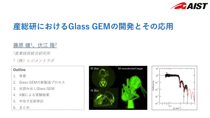
Ecb[X]T *
- XN9@
, XN9@
- .
- /
~
y>[Paa >C * h * - - PowerPoint PPT Presentation
y>[Paa >C * h * mn Ecb[X]T * XN9@ ,
* mn
Ecb[X]T *
, XN9@
~
▶ hu9@L*M
▶ XN9@k
N*O=IPc[X%D@C8%d[,1/%]+%.,*i.,-%*220 N+O?JPZPPaX%TbP[%D@C8%d[0+-%*i-%+)*, N,OJ=cXePP%TbP[%A@DIJ%d[2%**))0& **))0%+)*-
*))pXN9@
Ib]VT[TRbXRXT[S 5+)Z(R
T[TRb]PdP[P]RT L&Pg
XPgT[TRb] T
/1)a
&NeVNTRNWRcVU[VPNXRNQ[aXN9@
Takeshi Fujiwara
XN9@
spark
Crystal portion (Li2OSiO2) Photo Mask Via HF etching Cr sputter Grinder Metallize Cu (inside via also) Remove Cr in surface (remains in via)
HI IT[TRbXdT[g TdT: TPX]aX]dXP N-OJ=cXePP%TbP[%D@C8%101+)*1
Takeshi Fujiwara
Etching machine UV exposure machine DC sputtering machine for Cr Laser microscope Plating machine DC sputtering machine for Cu Polishing machine
Takeshi Fujiwara
HPr*/c
Takeshi Fujiwara
Takeshi Fujiwara
Takeshi Fujiwara
Takeshi Fujiwara
L/M:5::NTN%AFF@7999%*222
▶
Ar + CF4 is known as a good scintillation gas. Firstly reported by Fraga in 1999[6]
▶
Large amount of scintillation photons would be produced during Glass GEM’s high gain avalanche process
▶
Gas scintillation can optically readout with CMOS camera
4000 3000 2000 1000
Intensity
800 700 600 500 400 300 200
Wavelength (nm)
GcP]bcTXRXT]Rg :CEIRPTP
*)) .)
Takeshi Fujiwara
.2WRI 9RTeFRPaXVTU .2WRI 9RTeFRPaPUNTR
C:8*TPScb RPVT C:8+TPScb[XVb 8(:=-
>[Paa>C RPVT
FCJ HTPScbPS
aRX]bX[[PbX]
..=T
N+OJ=cXePP%TbP[%A]A8[Fga%d[..%]*)+)*/
▶
▶
▶
N1OJ=cXePP%TbP[%A@DIJ%[1%D0+)*, N2OJ=cXePP%TbP[%D@C8%1.)+)*0
XN9@
Outlook of the detector
Takeshi Fujiwara
Takeshi Fujiwara
Takeshi Fujiwara
▶ Reconstructed
▶ 2 sec exposure time ▶ Took 20 minutes ▶ Filtered back projection method ▶ GEMs can easily amplify small
▶ This feature of GEMs is highly
Takeshi Fujiwara
▶ uXN9@q ▶ uhl~,87G ▶ ,wxw h XN9@ w ▶ 7[XXNO[N[NRNXcNecRXP[R
Takeshi Fujiwara