
SLIDE 1
Proximity Signal Use
GE Energy Timothy S Irwin December 2005
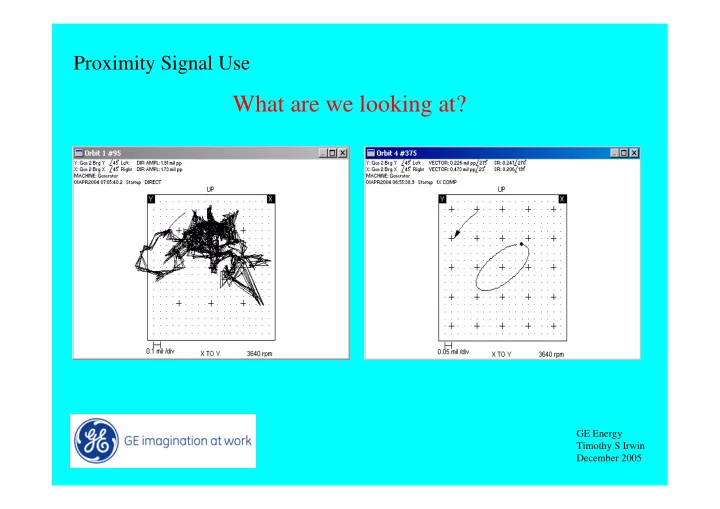
What are we looking at? GE Energy Timothy S Irwin December 2005 - - PowerPoint PPT Presentation
Proximity Signal Use What are we looking at? GE Energy Timothy S Irwin December 2005 Proximity Signal Use What are our Goals: Accurate information to provide: Machinery Condition Monitoring Machinery Diagnostics Machinery
GE Energy Timothy S Irwin December 2005
GE Energy Timothy S Irwin December 2005
GE Energy Timothy S Irwin December 2005
GE Energy Timothy S Irwin December 2005
GE Energy Timothy S Irwin December 2005
GE Energy Timothy S Irwin December 2005
GE Energy Timothy S Irwin December 2005
GE Energy Timothy S Irwin December 2005
GE Energy Timothy S Irwin December 2005
GE Energy Timothy S Irwin December 2005
GE Energy Timothy S Irwin December 2005
GE Energy Timothy S Irwin December 2005
GE Energy Timothy S Irwin December 2005
GE Energy Timothy S Irwin December 2005
GE Energy Timothy S Irwin December 2005
GE Energy Timothy S Irwin December 2005
GE Energy Timothy S Irwin December 2005
GE Energy Timothy S Irwin December 2005
GE Energy Timothy S Irwin December 2005
GE Energy Timothy S Irwin December 2005
GE Energy Timothy S Irwin December 2005
GE Energy Timothy S Irwin December 2005
GE Energy Timothy S Irwin December 2005
GE Energy Timothy S Irwin December 2005
GE Energy Timothy S Irwin December 2005
GE Energy Timothy S Irwin December 2005
GE Energy Timothy S Irwin December 2005
GE Energy Timothy S Irwin December 2005
GE Energy Timothy S Irwin December 2005
GE Energy Timothy S Irwin December 2005
GE Energy Timothy S Irwin December 2005