SLIDE 1 Welcome to Space Geodesy in Saudi Arabia
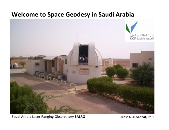
Saudi Arabia Laser Ranging Observatory SALRO
Nasr A. Al‐Sahhaf, PhD
SLIDE 2
SALRO to became a Global Geodetic Core Station Co‐locating multiple geodetic instruments, each providing for a different measuring technique allowing for data to be correlated thus providing improved accuracy and integrity
Saudi Arabian Space Geodesy Program Plan
For By means of
SLIDE 3
Geodetic Instruments for National and Global Reference Frames, Geodetic Research, Earth Science Studies and Space Exploration
Satellite Laser Ranging – SLR Global Positioning System – GPS Very Long Baseline Interferometry – VLBI Space Debris Tracking – SDT Continuous Operating GNSS Network– COGNET Lunar Laser Ranging – LLR
Program Active Future Plans
SLIDE 4
* Function The LLR is a geodetic instrument capable of measuring the distance between our Planet Earth and the Moon with a high degree of accuracy * Operation High energy laser pulses are transmitted to the Lunar surface and reflected back to the LLR‐ Observatory (Earth Station) from the retroreflector placed on the Moon during the Apollo Space Missions to measure the Time of Flight (TOF) * Measurement The LLR measures the Time Of Flight (TOF) of very short laser pulses traveling from the station to the Moon and back. Application LUNAR science, geodynamics, gravitational physics , astronomy and many more
Lunar Laser Ranging – LLR
SLIDE 5 NASA photo of Apollo Mission Laser Ranging Retro‐Reflector Picture of an LLR Observatory in New Mexico ranging to the Moon
Lunar Laser Ranging – LLR
The distance between the Earth and the Moon is calculated with a high degree of accuracy from the TOF Equation: d = c x t / 2 d distance, c formula for speed of light and t round‐trip of time of flight
TOF
SLIDE 6 Plot: LLR return signals
Credit: The Apollo Lunar Ranging Collaboration
SLIDE 7
* Function The SLR System is an instrument that forms part of a global network of stations measuring the orbital paths of geodetic satellites * Operation SLR transmits short laser pulses to geodetic satellites orbiting the Earth as they pass through the SLR Station field of view, these pulses are then reflected back from the satellites to the SLR System for Time Of Flight (TOF) measurements * Measurement TOF measurements are used to compute instantaneous range measurements to satellites with sub centimeter accuracy * Application Planetary Geodynamics supporting the International terrestrial reference frame (ITRF), scientific studies of the Earth its atmosphere and the oceans
Satellite Laser Ranging – SLR
SLIDE 8
SALRO ranging to satellite in orbit
What appears to be a continues laser beam is actually a train of very short pulses of less that 200 pico seconds The exact time of each pulse leaving the station and returning back is measured to determine the time of flight that is used to determine the distance between the station and the satellite
SLIDE 9
Global Network of SLR Stations
SALRO
SLIDE 10 * Function The Space Debris Tracking System is an instrument able to detect, identify and track space debris objects orbiting our Planet * Operation Different techniques are used for debris tracking: Like Space Optical Image Tracking, RADAR Tracking and LASER Tracking. Saudi Arabia is planning to make use of a Multimode LASER Tracking System * Measurement Different measuring techniques are used, with a multimode laser tracking system installed (SDT, LLR and SLR) Saudi will benefit from significantly enhanced data quality and integrity by correlating data obtained from the multiple techniques referenced to the same reference position (Monument) * Application To identify and track space debris (natural and man made) and to catalogue them in support
- f current and future space programs , space exploration and efforts to remove the debris
Space Debris Tracking – SDT
SLIDE 11 Satellites and Debris orbiting the Earth
Natural Debris: Small pieces of meteorites, coming from
- ur solar system and
- riginate from asteroids
and planetoids orbiting the Earth Artificial Debris: Man‐made objects like remains of spacecrafts, their payloads and hardware including fragments from collisions View from outside geosynchronous orbit
SLIDE 12
Global Positioning System – GPS
* Function A constellation of satellites that provides for radio signals to GPS receivers enabling them to calculate their positions * Operation GPS signals are received by the receivers, they processed these signals to determine their location in three dimensions * Measurement GPS satellites are equipped with high accurate timing systems synchronized to facilitate simultaneous transmission of position information. This information arrive at the at the GPS receiver at slightly different times. The receiver then measures and compute the phase relationship of these signals to determine its position with a high degree of accuracy *Application Navigation, Global terrestrial reference frame, mapping, monitoring of geodetic reference monuments, tracking and guiding of moving objects and many other geodetic applications
SLIDE 13
Geodetic Instruments co‐located at SALRO
SLR GPS
Co‐locating of space geodesy instruments adds value to the integrity of the data produced
SLIDE 14
SALRO‐IGN “Tie‐in” (Surveying Mission 2012)
Monuments, benchmarks and calibration piers have been surveyed with a high degree of precision as part of the “tie‐in” solution for the SALRO co‐located SLR and GPS (SOLA) instruments
SLIDE 15
Very Long Baseline Interferometry – VLBI
* Function The VLBI System is a radio telescope (Astronomical Interferometry Instrument) that allows for image observation of distant cosmic radio sources * Operation When the VLBI data is correlated with data collected from other Radio Telescopes simultaneously recorded they produce an image size of equal to the maximum separation between the telescopes serving as one giant telescope * Measurement VLBI Systems have very accurate timing systems typically hydrogen maser clocks to facilitate accurate measurements of the time differences between the arrival of cosmic radio sources (phase angle of the radio waves) at the separate observatories * Application Radio Astronomy, tracking of spacecrafts and many space geodesy science applications
SLIDE 16 VLBI observing a point source (Extra Terrestrial Radio Signal)
Extra terrestrial radio emissions comes from a variety of sources like the Sun, the Galactic center, Supernova, Pulsars, Quasars and many more
space
SLIDE 17 * Function COGNET is a network of GPS receivers that measures the differential positioning of various fixed terrestrial reference points * Operation Satellite navigation systems provide autonomous geo‐spatial positioning signals with global coverage, these signals when received by the GPS receiver are processed to produce positioning data * Measurement Carrier phase measurements are used in addition to pseudo ranges due to their superior accuracy to provide for accurate positioning data * Application To define the International terrestrial reference frame, for land, ocean and airspace navigation, steering and controlling of machine and man‐made moving
- bjects, mapping and many other applications
Continuous Operating GNSS Network– COGNET
SLIDE 18
KSA‐COGNET will serve as the backbone GNSS Network in the Kingdom providing a platform for high precision geodesy and Earth science applications. It will be compatible and in agreement with the International Terrestrial Reference Frame (ITRF) standards thus becoming part of the Global Network of GNSS Stations
COGNET ‐ Overview
SLIDE 19 The mission after theoretical calculations was to identify 16 sites for the COGNET infrastructure, in
the minimum density for a National CORS network. In addition to this we have selected 2 more sites to avoid any possible site related problems
KSA‐COGNET Scouting Mission
SLIDE 20
Amana ‐ Site Jizan ‐ Site Tayma ‐ Site Hail ‐ Site Saqaqa ‐ Site Sharurah ‐ Site Many factors were taken into consideration for selecting the best sites for the network, below is a brief list of some of the criteria taken into account during the scouting mission * Durability * Long term satellite visibility * Monument stability * Availability of power * Internet connectivity * Non‐interference signals * Low risk of future obstructions *Installation costs * Accessibility * Security
KSA‐COGNET Scouting Mission
SLIDE 21
Monument Specification for site installation
SLIDE 22 Data Processing with MicroCosm Software
Earth Rotation Solar Radiation Pressure Atmospheric Drag Polar Motion Earth Gravitation
Models
Solid Earth Tides Ocean Tides Ocean Loading Tropospheric Refraction Tectonic Plate Motion Earth Precession
Instrument Error Correction
Instrument Biases Monument Shift Instrument Clock and Timing
Geodetic Instruments
LLR GNSS SLR Measurement Ambiguities TDRS Noise Jitter Calibration DORIS Radar Alt.
SLIDE 23
Some of the key capabilities: Numeric integration of satellite parameters of motion for orbit prediction State vector estimation Atmospheric drag Solar radiation Time tag biases and station clock polynomials Tropospheric refraction Lunar, solar and planetary gravitational efficiencies Station coordinates Polar motion and Earth rotation Solid Earth and ocean tides Tectonic plate movement Simultaneous processing of multiple satellites per data arc
SLIDE 24
Saudi Arabia and its adjacent tectonic plates
Map: Illustrating the relationship between the Arabian and adjacent African, Indian and Eurasian tectonic plates Geodetic data needs to be processed to support scientific studies tin order o fully understand the tectonic plate activities and predict the influence it will have on man kind
SLIDE 25
Mechanical Design Electronic Design Optic and Laser Design * Precision optical mounts * High voltage enclosures * Special‐to‐type fixtures * Laser optical sub‐systems * Laser System
SALRO (SLR System)
* High voltage power supplies * Control and logic circuits * Fast photon detection circuits * Q‐switch control circuitry * Avalanche switching devices Patents pending
SLIDE 26 Mechanical Design
Pictures of some of the precision mechanical mounts locally developed and
was to meet with laser specific requirements
SLIDE 27
Electronic Design
Pictures of some of the electronic equipment locally developed Top left is 2 high voltage power supplies, in the middle is the new laser safety security system and at the bottom the new laser receive controller
SLIDE 28
Laser and Optical Design
Laser and optical development includes photo detection, mode‐ locking, q‐switching and optical sub‐ systems . Regret no pictures
SLIDE 29
Thank you
Nasr A. Al‐Sahhaf, PhD Director, Saudi Space Geodesy Center King Abdulaziz City for Science and Technology