
SLIDE 1
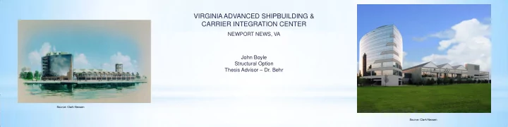
VIRGINIA ADVANCED SHIPBUILDING & CARRIER INTEGRATION CENTER
John Boyle Structural Option Thesis Advisor – Dr. Behr NEWPORT NEWS, VA
Source: Clark-Nexsen Source: Clark-Nexsen
VIRGINIA ADVANCED SHIPBUILDING & CARRIER INTEGRATION CENTER - - PowerPoint PPT Presentation
VIRGINIA ADVANCED SHIPBUILDING & CARRIER INTEGRATION CENTER NEWPORT NEWS, VA John Boyle Structural Option Thesis Advisor Dr. Behr Source: Clark-Nexsen Source: Clark-Nexsen ACKNOWLEDGEMENTS I would like to thank the following
Source: Clark-Nexsen Source: Clark-Nexsen
Source: Clark-Nexsen
Source: Clark-Nexsen
Source: Clark-Nexsen Source: Clark-Nexsen Source: Clark-Nexsen
Source: Clark-Nexsen Source: Clark-Nexsen
Source: Clark-Nexsen Source: Clark-Nexsen
Source: Clark-Nexsen Source: Clark-Nexsen
HEIGHT (CURRENT BUILDING) HEIGHT (REDESIGN)
0’-0” 0’-0”
17’-6” 17’-6”
32’-10” 32’-2”
47’-2” 45’-10”
61’-6” 59’-6”
75’-10” 73’-2”
90’-2” 86’-10”
104’-6” 99’-8”
126’-3” 122’-1”
Source: Clark-Nexsen Source: Clark-Nexsen
Height Kz qz P Height Difference F First 9 0.943 16.62 18.09 0.00 Second 26.5 1.137 20.05 20.84 17.5 91.60 Third 41.83 1.231 21.70 22.17 15.33 87.19 Fourth 56.16 1.296 22.85 23.09 14.33 87.43 Fifth 70.5 1.348 23.77 23.83 14.34 89.97 Sixth 84.83 1.393 24.54 24.45 14.33 92.11 Seventh 99.16 1.431 25.22 24.99 14.33 97.42 Penthous e 114.5 1.467 25.86 25.50 15.34 121.17 Roof 135.21 1.510 26.62 26.11 20.71 70.30