
SLIDE 1
FAIR GmbH | GSI GmbH
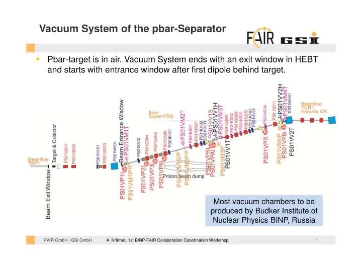
Vacuum System of the pbar-Separator
- Pbar-target is in air. Vacuum System ends with an exit window in HEBT
and starts with entrance window after first dipole behind target.
1
Most vacuum chambers to be produced by Budker Institute of Nuclear Physics BINP, Russia
- A. Krämer, 1st BINP-FAIR Collaboration Coordination Workshop