
SLIDE 1
Systems Design & Programming
- Micro. Arch. II
CMPE 310 1 (Feb. 2, 2002)
UMBC
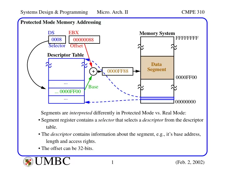
U M B C U N I V E R S I T Y O F M A R Y L A N D B A L T I M O R E C O U N T Y 1 9 6 6Protected Mode Memory Addressing Segments are interpreted differently in Protected Mode vs. Real Mode:
- Segment register contains a selector that selects a descriptor from the descriptor
table.
- The descriptor contains information about the segment, e.g., it’s base address,
length and access rights.
- The offset can be 32-bits.
Descriptor Table FFFFFFFF 00000000 DS 0008 Memory System Data Segment ... ... + EBX ... 0000FF00 0000FF00 0000FF88 Selector 00000088 Offset Base