
SLIDE 1
Triplet state diffusion in
- rganometallic and organic semiconductors
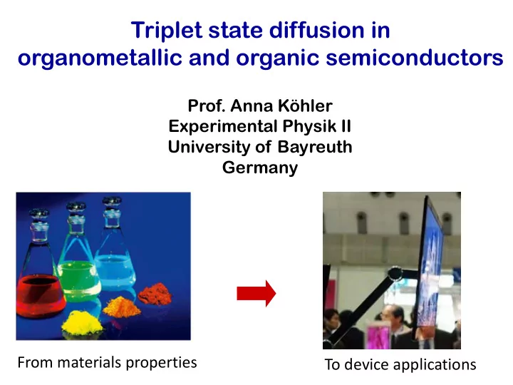
From materials properties To device applications
- Prof. Anna Köhler
Triplet state diffusion in organometallic and organic semiconductors - - PowerPoint PPT Presentation
Triplet state diffusion in organometallic and organic semiconductors Prof. Anna Khler Experimental Physik II University of Bayreuth Germany From materials properties To device applications Organic semiconductors allow for attractive displays
Opto‐electronic properties
flexible robust → novel products light‐weight soluble → new fabrication technologies conduction → transistors, absorption solar cells, emission light emitting diodes +
R R R R R R
strong coupling : bands weak coupling : localised states … … amorphous organic film large e‐h distance weak binding weak exchange energy high dielectric constant: low dielectric constant : small e‐h distance (≈0.3 nm) strong binding (≈0.4 eV) high exchange energy (≈0.7 eV) Inorganic crystal ‐ + + ‐
Density of states
initial
E final
glass V 100 nm ITO Ca
Operate LED Place spin 1/2 electrons and spin 1/2 holes in π and π* orbitals π π∗
Energy
HOMO LUMO Conduction‐states Valence‐states … …
glass V 100 nm ITO Ca
Operate LED Place spin 1/2 electrons and spin 1/2 holes in π and π* orbitals π π∗
Energy
π π∗
Energy
S1 T1 S0
Energy
1 spin = 0 : Singlet state emission allowed (fluorescence) 3 spin = 1 : Triplet state emission forbidden (phosphorescence) Singlet S1 Triplet T1 They form two types of states OR
ΔE ISC
Y.Sun + S. Forrest, Nature 2006 QEext=19 % , 30 lm/W for white OLED
Zhang, Köhler JCP 2006 p. 244701 06
Brunner, Van Dijken, JACS 2004
2,0 2,5 3,0 3,5 4,0 4,5
monomer polymer
T1 S1 Monomer Polymer
Energy
50 100 150 200 250 300
Polymer Monomer
10-2 10-1 100 Polymer Ea = 60 meV Monomer Ea = 100 meV 20 40 60 80 100 120 log (1/τ) (μs-1) 80 K 250 K 1000/T (K-1)
c
⎟ ⎠ ⎞ ⎜ ⎝ ⎛− kT EA exp ~
D+ A‐ Ea ΔG0 λ DA D+A‐
2
1 4 ⎥ ⎦ ⎤ ⎢ ⎣ ⎡ Δ + = λ λ G Ea
a if if
2
Activation energy Configuration Coordinate Energy λ = the reorganisation energy (electron‐phonon coupling) The transfer rate is given by:
λ ΔG*
a
Qj Epot
if if
2
2
1 4 ⎥ ⎦ ⎤ ⎢ ⎣ ⎡ Δ + = λ λ G Ea
a if if
2
λ ΔG*
a
Qj Epot
if if
2
2
1 4 ⎥ ⎦ ⎤ ⎢ ⎣ ⎡ Δ + = λ λ G Ea
a if if
2
Wavefunction overlap, good along chain
f
Qj Epot Brédas et al, Chem. Rev. 2004, 104, 4971; Markvart & Greef, JCP, 2004, 121, 6401
i f
rel f rel i rel
i
f
i
f
Qj Epot Brédas et al, Chem. Rev. 2004, 104, 4971; Markvart & Greef, JCP, 2004, 121, 6401
j j j j j rel rel
i f
S n n − − =
rel f rel i rel
i
f
i
0.0 0.2 0.4 0.6 0.8 1.0 1.2 Phosphorescence (a.u.) Polymer
0-0 0-1 0-2
1 3 6 7 5 4 +
1.8 2.0 2.2 2.4 2.6 0.0 0.2 0.4 0.6 0.8 1.0 1.2 Monomer
1 3 6 7 5
0-0 0-1 0-2
4 +
Energy (eV) Phosphorescence (a.u.)
mode 1 61 0.03 2 2 104 0.12 13 3 136 0.03 4 4 145 0.06 9 5 152 0.06 9 6 198 0.18 36 7 261 0.11 29
j
j
rel
j
100 = = ∑
j j j rel
S E ω h
meV
j j j rel
meV Polymer Monomer:
a if if
2
rel a
10-2 10-1 100 Polymer Ea = 60 meV Monomer Ea = 100 meV 20 40 60 80 100 120 log (1/τ) (μs-1) 80 K 250 K 1000/T (K-1)
c
From Analysis
from temp. dep.
a if if
2
rel a
Density of states
initial
E final
⎥ ⎥ ⎦ ⎤ ⎢ ⎢ ⎣ ⎡ ⎟ ⎟ ⎠ ⎞ ⎜ ⎜ ⎝ ⎛ − −
2
8 1 exp ~ T k T k E W
B B a e
σ
⎥ ⎥ ⎦ ⎤ ⎢ ⎢ ⎣ ⎡ ⎟ ⎟ ⎠ ⎞ ⎜ ⎜ ⎝ ⎛ −
2
2 1 exp ~ T k W
B e
σ High Temperature Low Temperature
⎟ ⎟ ⎠ ⎞ ⎜ ⎜ ⎝ ⎛ − + − − T k W
B i j i j ij
2 exp ~ ε ε ε ε
⎥ ⎥ ⎦ ⎤ ⎢ ⎢ ⎣ ⎡ − − − − − T k E T k T k E W
B a i j B i j B a ij
16 2 exp ~
2
ε ε ε ε
Multiphonon hopping Phonon‐assisted tunneling
5 10 15 20 25
log(We), (We in μs
1000/T (K
a/L=10
ν0=3x10
12 sec
J0=250 meV Ea=50 meV 0.05 0.20 0.25 0.30 0.10 0.15 0.50 0.70
σ/Ea
The two regimes, multiphonon hopping and phonon‐assisted tunneling, are no longer distinct! The exp (‐1/T2) dependence dominates the energy transfer ⎥ ⎥ ⎦ ⎤ ⎢ ⎢ ⎣ ⎡ ⎟ ⎟ ⎠ ⎞ ⎜ ⎜ ⎝ ⎛ −
2
2 1 exp ~ T k W
B e
σ
⎥ ⎥ ⎦ ⎤ ⎢ ⎢ ⎣ ⎡ ⎟ ⎟ ⎠ ⎞ ⎜ ⎜ ⎝ ⎛ − −
2
8 1 exp ~ T k T k E W
B B a e
σ
10 20 30 40 50
0,0 input parameters from experiment E a=60 meV, J=0.0174 meV, ν0=3x10
12 s
fitting parameters
σ=3 meV, a/L=9.6
Miller-Abrahams model (eq. 13) Marcus model (eq. 12) log10(We) , (We in μs
1000/T (K
transition temperature 80 K a
500 1000 1500 2000 2500
0.0 Marcus model (eq. 12) Miller-Abrahams model (eq. 13) log10(We) , (We in μs
(1000/T(K))
2
transition temperature 80 K b
High Temp.: Multiphonon hopping
Adiabatic, multiphonon hopping
Low Temp.: Phonon‐assisted tunneling
2,0 2,5 3,0 3,5 4,0 4,5 0,0 0,5 1,0 1,5 2,0 2,5 3,0 0,0 0,5 1,0 1,5 2,0 2,5 3,0 700600 500 400 300 PF PF PF Ph Ph DF DF DF Ph
C H3 C H3 CH3 CH3 nabsorption (arb. units) luminescence intensity (arb. units) Energy [eV] wavelength (nm) a)
0.00 0.02 0.04 0.06 0.08 0.10 1E-3 0.01 0.1 1 10 141meV
polymer trimer dimer 1/τ [ms
1/T [K
109 meV 215 meV 50 100 150 200 250 300 0,0 0,2 0,4 0,6 0,8 1,0
polymer trimer dimer normalized integrated phosphorescence intensity T [K]
Ea