Topic Weve talked about signals representing bits. How, exactly? - - PowerPoint PPT Presentation

topic
SMART_READER_LITE
LIVE PREVIEW

Topic Weve talked about signals representing bits. How, exactly? - - PowerPoint PPT Presentation

Topic Weve talked about signals representing bits. How, exactly? This is the topic of modulation Signal 10110 10110 CSE 461 University of Washington 1 A Simple Modulation Let a high voltage (+V) represent a 1, and low


slide-1
SLIDE 1

CSE 461 University of Washington 1

Topic

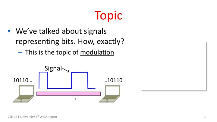
  • We’ve talked about signals

representing bits. How, exactly?

– This is the topic of modulation

…10110

10110…

Signal

slide-2
SLIDE 2

A Simple Modulation

  • Let a high voltage (+V) represent a 1, and low

voltage (-V) represent a 0

– This is called NRZ (Non-Return to Zero)

CSE 461 University of Washington 2

Bits NRZ

1 1 1 1 1 1 1 +V

  • V
slide-3
SLIDE 3

A Simple Modulation (2)

  • Let a high voltage (+V) represent a 1, and low

voltage (-V) represent a 0

– This is called NRZ (Non-Return to Zero)

CSE 461 University of Washington 3

Bits NRZ

1 1 1 1 1 1 1 +V

  • V
slide-4
SLIDE 4

CSE 461 University of Washington 4

Many Other Schemes

  • Can use more signal levels, e.g., 4

levels is 2 bits per symbol

  • Practical schemes are driven by

engineering considerations

– E.g., clock recovery »

slide-5
SLIDE 5

CSE 461 University of Washington 5

Clock Recovery

  • Um, how many zeros was that?

– Receiver needs frequent signal transitions to decode bits

  • Several possible designs

– E.g., Manchester coding and scrambling (§2.5.1) 1 0 0 0 0 0 0 0 0 0 … 0

slide-6
SLIDE 6

CSE 461 University of Washington 6

Clock Recovery – 4B/5B

  • Map every 4 data bits into 5 code

bits without long runs of zeros

– 0000 à 11110, 0001 à 01001, 1110 à 11100, … 1111 à 11101 – Has at most 3 zeros in a row – Also invert signal level on a 1 to break up long runs of 1s (called NRZI, §2.5.1)

slide-7
SLIDE 7

Clock Recovery – 4B/5B (2)

  • 4B/5B code for reference:

– 0000à11110, 0001à01001, 1110à11100, … 1111à11101

  • Message bits: 1 1 1 1 0 0 0 0 0 0 0 1

CSE 461 University of Washington 7

Coded Bits: Signal:

slide-8
SLIDE 8

Clock Recovery – 4B/5B (3)

  • 4B/5B code for reference:

– 0000à11110, 0001à01001, 1110à11100, … 1111à11101

  • Message bits: 1 1 1 1 0 0 0 0 0 0 0 1

CSE 461 University of Washington 8

Coded Bits: 1 1 1 0 1 1 1 1 1 0 0 1 0 0 1

slide-9
SLIDE 9

CSE 461 University of Washington 9

Passband Modulation

  • What we have seen so far is

baseband modulation for wires

– Signal is sent directly on a wire

  • These signals do not propagate well
  • n fiber / wireless

– Need to send at higher frequencies

  • Passband modulation carries a

signal by modulating a carrier

slide-10
SLIDE 10

CSE 461 University of Washington 10

Passband Modulation (2)

  • Carrier is simply a signal oscillating

at a desired frequency:

  • We can modulate it by changing:

– Amplitude, frequency, or phase

slide-11
SLIDE 11

Passband Modulation (3)

CSE 461 University of Washington 11

NRZ signal of bits Amplitude shift keying Frequency shift keying Phase shift keying

slide-12
SLIDE 12

CSE 461 University of Washington 12

Topic

  • How rapidly can we send

information over a link?

– Shannon capacity (1948) »

  • Practical systems are devised

to approach these limits

slide-13
SLIDE 13

CSE 461 University of Washington 13

Key Channel Properties

  • The bandwidth (B), signal strength

(S), and noise strength (N)

– B limits the rate of transitions – S and N limit how many signal levels we can distinguish Bandwidth B Signal S, Noise N

slide-14
SLIDE 14

CSE 461 University of Washington 14

Claude Shannon (1916-2001)

  • Father of information theory

– “A Mathematical Theory of Communication”, 1948

  • Fundamental contributions to

digital computers, security, and communications

Credit: Courtesy MIT Museum

Electromechanical mouse that “solves” mazes!

slide-15
SLIDE 15

Shannon Capacity

  • How many levels we can distinguish depends on S/N

– Or SNR, the Signal-to-Noise Ratio – Note noise is random, hence some errors

  • SNR given on a log-scale in deciBels:

– SNRdB = 10log10(S/N)

CSE 461 University of Washington 15

1 2 3 N S+N

slide-16
SLIDE 16

CSE 461 University of Washington 16

Shannon Capacity (2)

  • Shannon limit is for capacity (C),

the maximum information carrying rate of the channel: C = B log2(1 + S/BN) bits/sec

slide-17
SLIDE 17

Wired/Wireless Perspective

  • Wires, and Fiber

– Engineer link to have requisite SNR and B →Can fix data rate

  • Wireless

– Given B, but SNR varies greatly, e.g., up to 60 dB! →Can’t design for worst case, must adapt data rate

CSE 461 University of Washington 17

slide-18
SLIDE 18

Wired/Wireless Perspective (2)

  • Wires, and Fiber

– Engineer link to have requisite SNR and B →Can fix data rate

  • Wireless

– Given B, but SNR varies greatly, e.g., up to 60 dB! →Can’t design for worst case, must adapt data rate

CSE 461 University of Washington 18

Engineer SNR for data rate Adapt data rate to SNR

slide-19
SLIDE 19

Putting it all together – DSL

  • DSL (Digital Subscriber Line, see §2.6.3) is widely used

for broadband; many variants offer 10s of Mbps

– Reuses twisted pair telephone line to the home; it has up to ~2 MHz of bandwidth but uses only the lowest ~4 kHz

CSE 461 University of Washington 19

slide-20
SLIDE 20

DSL (2)

  • DSL uses passband modulation (called OFDM §2.5.1)

– Separate bands for upstream and downstream (larger) – Modulation varies both amplitude and phase (called QAM) – High SNR, up to 15 bits/symbol, low SNR only 1 bit/symbol

CSE 461 University of Washington 20

Upstream Downstream 26 – 138 kHz 0-4 kHz 143 kHz to 1.1 MHz Telephone Freq. Voice Up to 1 Mbps Up to 12 Mbps

ADSL2:

slide-21
SLIDE 21

CSE 461 University of Washington 21

Where we are in the Course

  • Moving on to the Link Layer!

Physical Link Network Transport Application

slide-22
SLIDE 22

CSE 461 University of Washington 22

Scope of the Link Layer

  • Concerns how to transfer messages
  • ver one or more connected links

– Messages are frames, of limited size – Builds on the physical layer

Frame

slide-23
SLIDE 23

Typical Implementation of Layers (2)

CSE 461 University of Washington 23

slide-24
SLIDE 24

CSE 461 University of Washington 24

Topics

1. Framing

– Delimiting start/end of frames

2. Error detection and correction

– Handling errors

3. Retransmissions

– Handling loss

4. Multiple Access

– 802.11, classic Ethernet

5. Switching

– Modern Ethernet

Later