
SLIDE 1
The Tokai to Kamioka Long Baseline Neutrino Oscillation Experiment
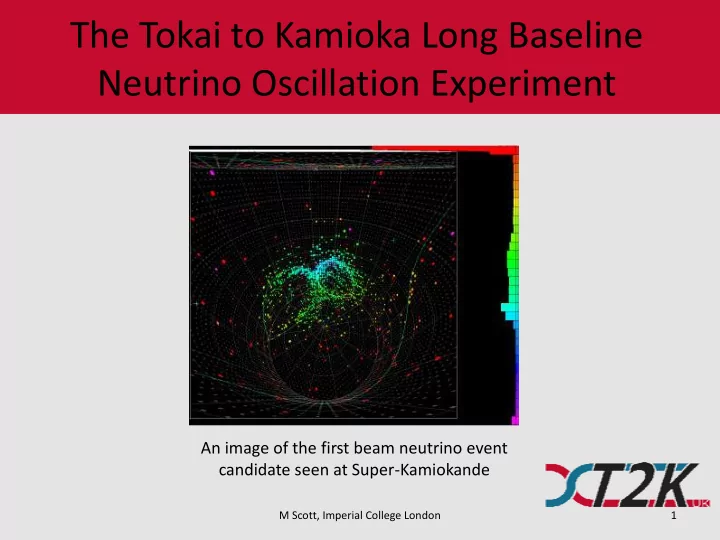
An image of the first beam neutrino event candidate seen at Super-Kamiokande
M Scott, Imperial College London 1
The Tokai to Kamioka Long Baseline Neutrino Oscillation Experiment - - PowerPoint PPT Presentation
The Tokai to Kamioka Long Baseline Neutrino Oscillation Experiment An image of the first beam neutrino event candidate seen at Super-Kamiokande M Scott, Imperial College London 1 Overview Theory of neutrino oscillations Experiment
An image of the first beam neutrino event candidate seen at Super-Kamiokande
M Scott, Imperial College London 1
M Scott, Imperial College London 2
i i i
3 1
1 1 1
12 12 12 12 13 13 13 13 23 23 23 23
c s s c c e s e s c c s s c U
i i i
M Scott, Imperial College London 3
E L m P
2 23 2 23 2 13 4
27 . 1 sin 2 sin cos 1 ) (
E L m P
e 2 13 2 23 2 13 2
27 . 1 sin sin 2 sin ) (
ij = m2 i – m2 j.
M Scott, Imperial College London 4
M Scott, Imperial College London 5
M Scott, Imperial College London 6
M Scott, Imperial College London 7
M Scott, Imperial College London 8
M Scott, Imperial College London 9
M Scott, Imperial College London 10
M Scott, Imperial College London 11
M Scott, Imperial College London 12
Neutrino energy spectrum for 1, 2 and 3 degrees off axis
M Scott, Imperial College London 13
M Scott, Imperial College London 14
Work done by M. George (QMUL) and G. Davies (Lancs.)
M Scott, Imperial College London 15
Work done by A. Waldron (Oxford)