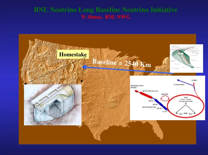
SLIDE 1 BNL Neutrino Long Baseline Neutrino Initiative
Baseline = 2540 Km
Homestake
SLIDE 2
WHERE WE ARE
– Making the physics case for the Very Long Baseline Neutrino Beam – Conceptualizing AGS upgrade schemes that will lead to high power (1+ MW) – Developing target/horn ideas – Embarking on an material R&D
SLIDE 3 BNL Long Baseline Neutrino Beam - Physics
The dominant term governing the
2 L / 4E)
Longer Length allows oscillations to be seen at higher Energy Cross sections are larger and energy resolutions are better at higher Energy A broad band beam allows coverage of multiple oscillation periods and observation
- f a distinct oscillation signature
The multiple node structure alows ∆m32
2 to
be precisely measured by a wavelength rather than an amplitude (reducing systematic errors)
SLIDE 4
BNL Super-Beam – Baseline Parameters
SLIDE 5
BNL Super-Beam – Baseline Parameters
SLIDE 6 BNL Target/Horn Working Concept
TARGET CONCEPTUAL DESIGN - CHALLENGES
- Carbon-Carbon composite target (80cm
long, 6mm radius)
- Selected over graphite for superior strength
and low thermal expansion
- Experimental verification of graphite and
carbon-carbon response
- Sublimation issues are potentially avoided
- Forced He gas in annular space cools
target operating at ~ 800C
- ∆T per 1014 proton pulse ~ 170o C
SLIDE 7 Carbon-Carbon Composite Target
Temp. % elongation 23 o C 0% 200 o C
400o C
600o C
800o C 0% 1000o C 0.040% 1200o C 0.084% 1600o C 0.190% 2000o C 0.310% 2300o C 0.405%
SLIDE 8
IS THERE AN OPTIMAL BEAM SIZE/TARGET SIZE RELATION ?
Two Beam sizes are considered – 1mm & 2mm beam spots (6mm & 12mm diam. targets respectively) Total energy deposited on target is 5.1 & 7.3 kJ respectively Corresponding peak DTs on target are 960 C and 260 C Yield of secondaries is being optimized. That may lead to a beam spot/target diameter somewhere in between Option of Gaussian beam to flat beam is also assessed
SLIDE 9 BNL Target/Horn Working Concept
- Baseline material is Aluminum (6061 T6 or 3000 series)
- New alloys are considered (e.g. AlBeMet)
- Task is keeping resistivity low while maintaining strength as
well as resistance to fatigue, corrosion
- Heat transfer through water spray (baseline)
- Horn inner conductor diameter = 14mm
- Conductor thickness narrowest section = 2.5mm
- Smallest horn thickness = 1mm
HORN CHALLENGES
- Current pulse structure - Joule heating
- Gamma ray heating - long term irradiation effects
- Material degradation due to forced water cooling
combined with thermal fatigue
- Maintaining operating temperature at safe levels
SLIDE 10
CHALLENGES FOR THE INTEGRATED TARGE/HORN SYSTEM AS WE GET TO 1+ MW SYSTEM Heat generation and removal from the target/horn system Target thermo-mechanical response from energetic, high intensity protons Irradiation and corrosion effects on materials Horn/target integration issues Horn mechanical response and long term integrity (irradiation, corrosion and thermal fatigue) Beam windows integrated in the system to (a) separate the vacuum space in the transfer line from the final beam line to the target and (b) to maintain the coolant around the target in a close-system loop
SLIDE 11
SLIDE 12
SLIDE 13
SLIDE 14
Horn temperature transients Temperature distribution for HORN/Target in contact
SLIDE 15
OPTIMIZATION EFFORT TO MEET THE CHALLENGE OF 1+ MW SYSTEM
Alternative new materials (e.g. AlBeMet, Toyota “Gum Metal”, etc) are being considered and will be experimentally evaluated Nano-structured surface film embedment is being considered as option to protect the horn base-material – Examine other techniques for surface treatment (e.g. culsterizing ???) Heat transfer enhancement is being evaluated through the use of nano- particles in the cooling medium
SLIDE 16 Relevant Lessons from BNL E951 Experiment Set out to assess:
- Solid target survival chances (graphite, carbon-carbon, inconel,
superInvar, etc.)
- Beam window survival (critical due to Hg)
And while at it ……
- Push the AGS intensity to 16 TP and beam spot to 0.5 mm RMS sigma
- Experiment with and identify best candidate materials through
measured responses
- Validate prediction models against measurements to gain confidence in
predicting material response and/or failure at extreme conditions
- Use experimental results to benchmark energy depositions predicted by
the various Monte Carlo codes
SLIDE 17
E951Target Station Set-Up Graphite & Carbon-Carbon Targets
SLIDE 18 ATJ Graphite Strain Data
Verification of fundamental modes of target response
Recorded strains in the middle of the graphite rod (left) shows a bending frequency between 380-390 Hz The prediction of the detailed model that implements the supporting/holding fixtures of the target as close to the real setting as possible, predicts a bending frequency of 395 Hz Also from the record, the axial “ringing” of the target has a period of 260 to 265 microseconds. The fundamental axial period T=2L/c (where L is target rod length and c is speed of sound) is approximately 261 microseconds The radial “ringing” on the other hand, which from theory is calculated at 150 KHz (or 6.625 microsecond period), is visible only in the strain record filtered by the 500 KHz acquisition
SLIDE 19
ATJ Graphite Strain Data
SLIDE 20 ATJ Graphite Strain Comparison
BASIS FOR HADRON CALCULATIONS BENCHMARKING
SLIDE 21 ATJ Graphite Strain Comparison
BASIS FOR HADRON CALCULATIONS BENCHMARKING
SLIDE 22 ATJ Graphite vs. Carbon-Carbon Composite
BNL E951 Target Experiment 24 GeV 3.0 e12 proton pulse on Carbon-Carbon and ATJ graphite targets Recorded strain induced by proton pulse
2 4 6 8 10 0.0002 0.0004 0.0006 0.0008 0.001 Time (sec) Microstrain C-C composite ATJ Graphite
SLIDE 23
Recent BNL Irradiation Studies on Super Invar & Inconel-718
SLIDE 24
Irradiation Studies at BNL
SLIDE 25 Super-Invar Irradiation Study
WHY STUDY super Invar ?
- High-Z with low CTE (0-150 oC)
- How is CTE affected by radiation?
- What happens to other important properties?
SLIDE 26
Summary
Solid Target Option: Super-Invar Irradiation Study
SLIDE 27 Super-Invar Irradiation Study – Temperature Effects
Effect of Heat Treatment in non-Irradiated Invar Samples
500 1000 1500 2000 2500 0.05 0.1 0.15 0.2 0.25 Extension (mm) Load (N)
non treated Invar Temp (300 C) Temp (500 C)
SLIDE 28
Super-Invar Irradiation Study – CTE assessment
Super-Invar
Inconel 718
SLIDE 29 WHAT’S NEXT ?
- Assessment of long-term survival of baseline target & horn
materials (Aluminum & Carbon-Carbon)
- Repeat irradiation/mechanical property changes experiment
for baseline materials
- Experimentally verify the compatibility of cooling agents
with baseline materials (corrosion, sublimation)
- Explore innovative schemes to enhance heat transfer and
material protection (nano-structured films, nano-fluids, etc.)
- Explore new materials such as AlBeMet, Toyota’s “Gum
Metal” Titanium Alloy, Vascomax, Titanium (6Al-6Va)
- Explore the possibility of using He for heat removal for the
integrated target/horn system
SLIDE 30
What are some of these new materials we plan to examine ?