SLIDE 1
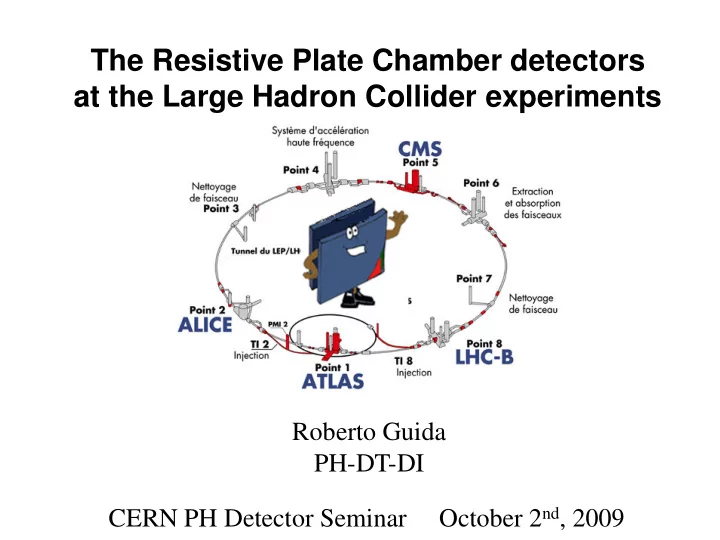
The Resistive Plate Chamber detectors at the Large Hadron Collider experiments
Roberto Guida PH-DT-DI CERN PH Detector Seminar October 2nd, 2009
SLIDE 2 Introduction to the RPC detector
- Where are the RPC detectors at LHC
- Main parameters for the design
From the design to the production:
- An “industrial approach”
- Quality control procedure
Requirement for RPC operation at LHC
Outline
Requirement for RPC operation at LHC
- Effect of background radiation
- Rate capability/detector occupancy
- Long-term performance – ageing issues
Experience on operation of RPC detectors:
- Importance of the gas mixture quality
- Effect of the environmental conditions (T + RH)
- Gas leak
Conclusions
SLIDE 3 Introduction to the RPC detector
- Where are the RPC detectors at LHC
- Main parameters for the design
From the design to the production:
- An “industrial approach”
- Quality control procedure
Requirement for RPC operation at LHC
Outline
Requirement for RPC operation at LHC
- Effect of background radiation
- Rate capability/detector occupancy
- Long-term performance – ageing issues
Experience on operation of RPC detectors:
- Importance of the gas mixture quality
- Effect of the environmental conditions (T + RH)
- Gas leak
Conclusions
SLIDE 4 The RPC detector
Resistive Plate Counters resistive parallel plate gaseous detector Developed around 1980 in Italy by R. Santonico et al. NIM 187 (1981) 377-380
- 1. Electrodes: HPL made with melamine/phenol resins; Glass; Ceramic
- Resistive electrodes: 1010- 1012 Ωcm
- Internal electrode surface covered with a thin linseed oil layer (~µm)
- 2. Gap width: 2 mm
- 3. High Voltage contacts: graphite paint (~100 µ
µ µ µm)
- Operating pressure: atmospheric pressure
- Gas mixture: Ar, C2H2F4, iC4H10, SF6
- Gas flow: 0.2 vol/h
- Dimensions: Surface: ~ m2, thickness: 1 cm
- Read-out strip: Al/Cu, ~cm
SLIDE 5 Ionizing particles passing through the gas are producing primary ionization Primary electrons accelerated in the electric field will start to produce further ionization
x dE ∆
Working principle
i i total
W x dx dE W E n ∆ = ∆ =
primary total
n n ⋅ ≈ 4 ... 3
ntotal: total number e-/Ion ∆E: total energy loss Wi: <energy loss>/(total number e-/Ion)
SLIDE 6 Primary e-
[ ]x
E
e n x n
β α −
=
) (
) (
Charge multiplication
α= first Townsend coefficient β= attachment coefficient η = α-β = effective Townsend coefficient Gain
= =
∫
d
dx x n n M ) ( exp η
η = α-β = effective Townsend coefficient αx ∼ 20 M ∼ 108 Reather breakdown limit
SLIDE 7 Why the RPC?
Drift chambers (cylindrical geometry) have an important limitation: Primary electrons have to drift close to the wire before the charge multiplication starts limit in the time resolution ∼ 0.1µs Not suitable for trigger at LHC + In a parallel plate geometry the charge multiplication starts immediately (all the multiplication starts immediately (all the gas volume is active). + much better time resolution (∼ 1 ns) + less expensive (∼ 25 €/m2) However:
- Smaller active volume
- Electrical discharge may start more easily
- Relatively expensive gas mixture
- Quite sensitive to environmental
conditions (T and RH)
SLIDE 8 1949: Keuffel first Parallel Plate Chamber 1955: Conversi used the “PPC idea” in the construction of the flash chambers 1980: Pestov Planar Spark chambers – one electrode is resistive – the discharge is localised 1982: Santonico development of the Resistive Plate Chamber – both electrode are resistive
Some history
RPC applications:
‘85: Nadir (n-n\bar oscillation) – 120 m2 (Triga Mark II – Pavia) ‘90: Fenice (J/Ψ n-n\bar) – 300 m2 (Adone – Frascati) ‘90: WA92 – 72 m2 (CERN SPS) ‘90: E771– 60 m2; E831 – 60 m2 (Fermilab) 1992: development of RPC detector suitable to work with high particle rate
- towards application at LHC
1994-1996: L3 – 300 m2 (CERN-LEP) 1996-2002: BaBar – 2000 m2 (SLAC)
SLIDE 9 Are the most important improvement with respect to previous generations
Why resistive electrodes?
Ionizing particle
Time constant for charge development is related to drift velocity and multiplication Time constant for recharge the elementary cell is related to the RC
ττ
Since τrecharge >> τdischarge the arrival of the electrons on the anode is reducing the electric field and therefore the discharge will be locally extinguished. the electrode are like insulator after the first charge development Self-extinguish mechanism
τdischarge = 1/ηvd ~ 10 ns τrecharge =ρε ~ 10 ms
SLIDE 10 Towards a new operation regime
Originally RPC were operated in Streamer mode:
Ar-based mixture Higher signal (100 pC) but also high current in the detector Voltage drop at high particle rate loss of efficiency poor rate capability (< 100 Hz/cm2)
Operation with high particle rate possible in Avalanche mode:
Freon-based mixture lower signal (∼ pC) but also lower current in the detector Less important high voltage drop at high particle rate good rate capability (∼
∼ ∼ ∼ 1 kHz/cm2) Avalanche signal Streamer signal
Less important high voltage drop at high particle rate good rate capability (∼
∼ ∼ ∼ 1 kHz/cm )
ATLAS Muon TDR
SLIDE 11 RPCs for LHC experiments
Where are the RPCs systems at LHC? ATLAS experiment:
- Single gap Bakelite RPC
- Barrel
- η-ϕ read-out
- Active surface 4000 m2
- Active surface 4000 m
- Expected rate ~ 10 Hz/cm2
Gas system:
- Volume 16 m3
- 94.7% C2H2F4; 5% iC4H10; 0.3 % SF6
- 40% Rel.Humidity
- Closed loop operation
- Circulation flow 0.5-1 vol/h
- 5-10% renewal
SLIDE 12 CMS experiment:
RPCs for LHC experiments
Where are the RPCs systems at LHC?
- Double gap Bakelite RPC
- Barrel and Endcap
- ϕ read-out
- Active surface 4000 m2
- Active surface 4000 m2
- Expected rate ~ 10-100 Hz/cm2
Gas system:
- Volume 16 m3
- 94.7% C2H2F4; 5% iC4H10; 0.3 % SF6
- 40% Rel.Humidity
- Closed loop operation
- Circulation flow 0.5-1 vol/h
- 5-10% renewal
SLIDE 13 RPCs for LHC experiments
Where are the RPCs systems at LHC? ALICE experiment: Muon Trigger System
- Single gap Bakelite RPC
- Forward Muon Spectrometer
- x-y read-out
- x-y read-out
- Active surface 140 m2
- Expected rate ~ 10 Hz/cm2
Gas system:
- Volume 0.3 m3
- 50.5%Ar; 41.3% C2H2F4; 7.2% iC4H10; 1 % SF6
- 89.7% C2H2F4; 10% iC4H10; 1 % SF6
- 40% Rel.Humidity
- Open mode
- Flow 0.5-1 vol/h
SLIDE 14 RPCs for LHC experiments
Where are the RPCs systems at LHC? ALICE experiment: Time of Flight System
- Multi-gap glass RPC
- Barrel
- η-ϕ read-out
- Active surface 171 m2
- Active surface 171 m2
Gas system:
- Volume 18 m3
- 90% C2H2F4; 5% iC4H10; 5 % SF6
- 93% C2H2F4; 10% iC4H10; 1 % SF6
- Closed loop operation
- Circulation flow 0.06 vol/h
- 2% renewal
SLIDE 15 RPCs for LHC experiments
Why RPCs for application in LHC experiments need a particular “care”?
Huge (∼5000 m2 of sensitive area) and very expensive (6 106 CHF) systems (for comparison BaBar was about 2000 m2) Very long period of operation expected (at least 10 years) Very high level of background radiation expected Integrated charge never reached before: 50 mC/cm2 for ALICE and CMS 500 mC/cm2 in ATLAS Large detector volume basically impossible to operate the gas system in
- pen mode closed loop operation gas mixture quality
SLIDE 16 Introduction to the RPC detector
- Where are the RPC detectors at LHC
- Main parameters for the design
From the design to the production:
- An “industrial approach”
- Quality control procedure
Requirement for RPC operation at LHC
Outline
Requirement for RPC operation at LHC
- Effect of background radiation
- Rate capability/detector occupancy
- Long-term performance – ageing issues
Experience on operation of RPC detectors:
- Importance of the gas mixture quality
- Effect of the environmental conditions (T + RH)
- Gas leak
Conclusions
SLIDE 17
Identikit of RPC detectors for LHC
Basic parameter for a detector design:
Gap width Single gap/double gap/multi gap design Gas mixture Gas mixture Gas flow distribution Bakelite bulk resistivity Linseed oil electrode coating
SLIDE 18 The RPC detector: gap width
The gap width is affecting both
time performance charge distribution
R = λ/η
λ cluster density (primary clusters) ηg =const = 18
Narrow gap better time resolution, but “more critical” charge spectrum (R seems to be the driving parameter) reduce number of primary electrons
R > 1 R < 1
- M. Abbrescia et al. NIMA 471 55-59
SLIDE 19
The RPC detector: single vs double gap
The double gap layout: allow to operate at lower η (i.e. lower high voltage) best ration qind/qtot (single 0.7; double 1.4; 3 gaps 0.8) Better charge distribution More expensive per unit of active area
SLIDE 20
Formation of the induced signal
Equivalent circuit of double RPC near the discharge region: Ratio between total charge and induced charge on the strips:
SLIDE 21 The RPC detector: gas mixture
Key parameters:
λ cluster density (primary clusters) – only gas dependent α first Townsend coefficient (charge multiplication) – gas, HV dependent β attachment coefficient – gas (electronegative and/or quencher), pressure dependent η effective Townsend coefficient = α - β
High λ gas:
high efficiency and low streamer probability at the same η! high efficiency and low streamer probability at the same η! i.e. for avalanche regime: better Freon (λ = 5.5 mm-1) than Ar (λ = 2.5 mm-1)
η
Voltage increasing
SLIDE 22 The RPC detector: gas mixture
Key parameters:
Moreover quencher (iC4H10) and electronegative (SF6) gases will help in containing the charge development and reducing the streamer probability Charge distribution: avalanche streamer
NIMA 508 142-146 Fraction of streamer vs High voltage:
- R. Santonico Scientifica Acta Pavia
SLIDE 23 The RPC detector: gas mixture
Key parameters:
Large λ are giving also a better charge distribution (constant η) λ ≤ 4 mm-1 spectrum monotonically decreasing Charge spectrum vs λ Streamer probability
- M. Abbrescia et al. NIMA 431 413-427
SLIDE 24 The RPC detector: gas flow distribution
Experience says that the gas flow has to be at least ∼ 0.3 vol / h even without radiation Is the gas distribution inside the gap the origin of this limit? Is there a space for future improvements? Some preliminary results coming from a finite element simulation:
Waldemar Maciocha Antonio Romanazzi Thanks to
spacers inlet
The velocity field shows areas in which the gas is hardly moving Gas velocity (m/s) inlets
SLIDE 25 RPC detector: Bakelite resistivity
The detector rate capability is strongly dependent on the Bakelite resistivity. At high particle rate (r) the current through the detector can become high enough to produce an important voltage drop (Vd) across the electrode: s: electrode thickness <Qe>: average pulse charge ρ: bakelite resistivity
ρ rs Q V
e d
2 =
ρ: bakelite resistivity In order not to lose efficiency Vd < ∼10 V Therefore ρ ~ 1010 Ω cm The time constant of an elementary cell is lower at lower resistivity: the cell is recovering faster (it is quicker ready again) after a discharge took place inside it.
( )ρ
ε ε τ 2 + =
r
SLIDE 26 RPC detector: linseed oil surface treatment
What is the linseed oil:
Drying oil (consists basically of triglycerides) Drying is related to C=C group in fatty acid Cross-linking (polymerization) in presence
- f air (O2 play important role) due to C=C
RPC electrodes are usually treated with linseed oil:
better quality of the internal electrode surface it acts as a quencher for UV photons better detector performance …but… More time needed during construction Ageing problems? (Not observed)
- f air (O2 play important role) due to C=C
SLIDE 27
RPC detector: linseed oil surface treatment
Few SEM photos (S.Ilie, C.Petitjean EST/SM-CP EDMS 344297): Defect on Bakelite surface possibly covered with linseed oil Thickness of the layer: ~ 5 µm The linseed oil layer is damaged by a surface outgassing
SLIDE 28 RPC detector: linseed oil surface treatment
Effect on UV photons hitting the electrode internal surface: Linseed oil absorbance UV sensitivity for coated and non coated Bakelite 8 eV 5.6 eV
C.Lu NIMA 602 761-765 P.Vitulo NIMA 394 13-20
SLIDE 29 RPC detector: linseed oil surface treatment
Chamber Performance: With linseed oil coated electrodes Lower current (∼1/10) Lower noise rate (∼1/10)
- M. Abbrescia et al. NIMA 394 13-20
SLIDE 30
The RPC detector
Summary
Gap width 2 mm: Good compromise between good efficiency, time resolution and rate capability More gaps: Increase time resolution and efficiency Double gap design: Double gap design: Best ratio induced/drift charge, therefore best signal/charge ratio Freon based mixture: Higher efficiency (at the same gas gain) and lower streamer probability Bakelite bulk resistivity = 1-6 1010 Ω cm: Good compromise between high rate capability and low current and noise Linseed oil treatment: Lower current and noise rate. No ageing effect observed
SLIDE 31 Introduction to the RPC detector
- Where are the RPC detectors at LHC
- Main parameters for the design
From the design to the production:
- An “industrial approach”
- Quality control procedure
Requirement for RPC operation at LHC
Outline
Requirement for RPC operation at LHC
- Effect of background radiation
- Rate capability/detector occupancy
- Long-term performance – ageing issues
Experience on operation of RPC detectors:
- Importance of the gas mixture quality
- Effect of the environmental conditions (T + RH)
- Gas leak
Conclusions
SLIDE 32 RPCs production and quality certification involve several steps.
ISR GT Bari Pavia Sofia
HPL production and quality control
RPC Barrel Production and Test Sites
Chamber test Sites RB1 in Pavia RB2 & RB4 in Bari RB3 in Sofia (& Bari)
Chamber assembling Sites
120 RB1 at HT 240 RB2 and RB4 at GT 120 RB3 in Sofia (& Bari)
Double gap
GT
Single gap
GT HT
SLIDE 33 QC5
Chambers
QC4 Double gaps
Further information and results about all QC are stored in our construction database: http://webcms.ba.infn.it/rpc
CMS-RPC Quality Control
Double gaps QC3 Single gaps
QC2 Bakelite and components
SLIDE 34 QC2: The “Bakelite” for RPC detector
More precisely the RPC electrodes are made on High Pressure Laminate: Several layers of ordinary paper Passed into a resin bath Heated and compressed Finally cut HPL top and bottom layer produced with more refined paper Resin bath:
- Made of phenolic and/or melamine resins
- Made of phenolic and/or melamine resins
- Different ratio according to the desiderate bulk resistivity
- In general, outer layers passed in phenolic resin only (again “low” resistivity)
All the Bakelite for RPCs has been produced in Italy: Chimica Pomponesco (later on Frati Laminati) near Pavia After the production Quality control
Resistivity range ρ ρ ρ ρ20 = 1- 6 1010 Ω Ω Ω Ω cm Average Roughness range Ra ≤ 0.2 µm 4000 slabs produced (about 15000 m2)
SLIDE 35 Resistivity control after production
70%
SLIDE 36 Bulk resistivity ρ ρ ρ ρ
Determines the time constant of an elementary RPC cell, τ τ τ τ = ε ε ε ε0 (ε ε ε εr + 2 ) ρ ρ ρ ρ and the rate capability
Production Measurement Data acquisition
The Bakelite quality control
Average roughness Ra
It is related to the quality of the surface. A small Ra reduces spontaneous discharges which might affect the RPC rate capability
Dielectric constant ε ε ε εr
It is related to τ τ τ τ and to the average fast charge qe of a single avalanche
Protocol Storage Out of range
SLIDE 37 The idea for the automatic system was to have the possibility:
- 1. to measure on 9 different points of the slabs
- 2. to use guard rings and hence
- 3. to measure also the surface resistivity
- 4. to increase the measurements productivity up to > 100 slabs/day
V0
How to measure ρ ~ 1010 - 1011 Ω cm
V0 V R
ρ = k V0/(V/R) k = geometrical factor (98.17) V0 = 500 V R = 10 or 100 kΩ
SLIDE 38
The slab is loaded and moved to the measurement position by the conveyors bed The slab is loaded and moved to the measurement position by the conveyors bed
Table moved in a tent with T and RH controlled (photo just after the installation)
The automatic system for ρ measurement
(photo just after the installation)
SLIDE 39 Ra:
Vertical deviation of the surface from its average profile
Bakelite surface roughness
Old bakelite
Measurements points on the surface
New bakelite
- P. Vitulo et al. Scientifica Acta Pavia 1995
SLIDE 40 Bakelite ageing study
Resistivity vs integrated (γ) dose at GIF and neutron irradiation at reactor ∝ ρ
8 Gy
- S. Altieri et al. NIMA 456 132-136
dry gas flow? recovery time needed?
SLIDE 41 Gas leakage& Overpressure
1st test
Leak test and Spacers test 20 mbar overpressure: visual inspection No pressure drop in 15 minutes Current test: I vs HV (1 kV steps every 15 min)
QC3: Single Gaps
81%
Overpressure
SG Accepted Current vs HV
2nd test
SG Rejected 2
STOP
SG Rejected 1
Current test: I vs HV (1 kV steps every 15 min) Current monitoring for about 2-3 hours at 9.5 kV
Acceptance criteria:
I < 5uA per gap at 9.5 kV Since April ’04… High voltage scan and data acquisition based on field-point system interfaced with Labview Current monitoring with 0.1 uA sensibility Current monitoring for about 12 hours at 9.5 kV DG production
SLIDE 42 Current test: I vs HV (1 kV steps every 15 min)
Acceptance criteria:
I < 5uA per gap at 9.5 kV Since April ’04…
QC4: double gaps
96% Since April ’04… High voltage scan and data acquisition based on field-point system interfaced with Labview Current monitoring with 0.1 uA sensibility Current monitoring for about 12 hours at 9.5 kV Since December ’04… New leak test after DG assembling
SLIDE 43 1) Construction site (HT-GT-SOFIA):
- Leak test
- Strip connectivity and LV
- Cooling test
- Current vs High Voltage (Acceptance criteria: I < 5uA per gap at 9.5 kV)
Chambers debug (before starting the cosmic test):
- adjusting threshold values (compromise between noise rate and efficiency)
- look at strip profile to find if there are dead strips or delayed strips,
disconnected cables, noisy FEB. Dead strips are repaired.
QC5: chamber test
> 96%
- Current vs High Voltage (Acceptance criteria: I < 5uA per gap at 9.5 kV)
- Current monitoring at fixed HV for 12-24 hours
2) Cosmic test site (Bari-Pavia-Sofia):
- Current vs High Voltage (Acceptance criteria: I < 5uA per gap at 9.5 kV)
- Current monitoring (at 9.6 kV) for 10 days
- Chamber performance: efficiency, noise, cluster size in single and double gap.
3) Final test at ISR: Current stability for about 15-20 days Noise test Leak test
SLIDE 44 Cosmic muon telescope
ε Efficiency distribution: tracking reconstruction vs coincidence
SLIDE 45 Tot produced Fully tested Accepted QC3 rejection 2359 2000 1627 (81 %) 373 (19 %)
QC3 Single Gaps: accepted-rejected
Produced Accepted QC4 Rejection 768 735 33 (4.3 %)
QC4 Double Gaps: accepted-rejected
768 735 33 (4.3 %)
ISR Leak current
Bari/Pavia/Sofia Leak current
HT/GT Leak current
Ch type 1 1 1 3 3 RB1 2 5 1 1 1 1 3 RB2/4 2 1 5 RB3 1 1 1 1 RB4
QC5 Chambers: accepted-rejected
SLIDE 46
First period October- Dec 03 Flushing with final gas mixture for one day before starting HV tests (Flow rate 8 l/h per chamber) HV conditioning:
ISR Test: procedure
Current vs Voltage curve Current stability check at 9.2 kV for 15-20 days. New procedure since 04: flushing for at least 5 days before switching ON the HV.
SLIDE 47 Bk Fw
1 HV connection for 2 gaps: layer up = Fw Up + Bk Up layer down = Fw Dw + Bk Dw
RPCs data quality monitoring
Max efficiency Current Layer up <I> = 2.3 µA Noise rate < 5 Hz/cm2
- M. Abbrescia et al. NIMA 550 116-126
SLIDE 48 HV @ 9.6 kV
Cluster Size
Mean Cluster size distribution Mean Cluster size distribution HV @ 9.6 kV Mean Cluster size vs HV Mean Cluster size vs HV
SLIDE 49 Chamber spatial resolution can be evaluated, using the residual distribution (distance between muon impact point and the nearest cluster center). Spatial resolution for this chamber is ~ 8.1 mm (in good agreement with theoretical one ~7.9 mm)
Spatial resolution (global properties)
SLIDE 50
Muon reconstruction: local properties
Efficiency strips profile Local inefficiency
After superimposing data from different, but aligned, slices, the 100 mm spacers structure is visible (local inefficiency)
Local inefficiency due to spacers
SLIDE 51 Introduction to the RPC detector
- Where are the RPC detectors at LHC
- Main parameters for the design
From the design to the production:
- An “industrial approach”
- Quality control procedure
Requirement for RPC operation at LHC
Outline
Requirement for RPC operation at LHC
- Effect of background radiation
- Rate capability/detector occupancy
- Long-term performance – ageing issues
Experience on operation of RPC detectors:
- Importance of the gas mixture quality
- Effect of the environmental conditions (T + RH)
- Gas leak
Conclusions
SLIDE 52 Effects of background radiation
Detector occupancy: Two mechanisms: instantaneous particle rate detector occupancy cumulative effects ageing
It is imperative that the design of a pp experiment at the LHC takes account of the hostile radiation environment engendered at high luminosity
(CMS Letter of Intent, CERN-LHCC 92-3, 1 Oct. 1992)
Detector occupancy:
- Related to the background radiation detector efficiency
- RPC are very efficient in detecting charged particle
- Efficiency for neutral radiation is very low…but if the particle rate is
high enough… Ageing:
- Related to the integrated particle fluence, dose and current in the
detector
SLIDE 53 Charged background
CMS Max flux: Barrel ~ 10 Hz/cm2 Forward ~ 50-100 Hz/cm2 Barrel ATLAS Max flux: Barrel ~ 5 Hz/cm2 Forward ~ 10 Hz/cm2 Forward
µ, p fluxes in Hz/cm2 n, γ fluxes in kHz/cm2
SLIDE 54 Max flux: Barrel ~ 460 Hz/cm2 Forward ~ 10-50 kHz/cm2 Energy: between 20 keV - 100 MeV
Neutral background
Barrel Forward CMS experiment CMS-RPC total integrated charge for Barrel region 50 mC/cm2 Max Integrated dose 10 years: (Barrel and most Forward) < 1 Gy
SLIDE 55 Detector occupancy
Given the expected background (particles + fluxes) we have: Measured the RPC sensitivity to it Performed simulation study for the final configuration on the experiment
- 35 x 35 cm2 double gap RPC:
RPC used for the sensitivity measurement:
- 35 x 35 cm double gap RPC:
- Gap 1 oiled
- Gap 2 not oiled
SLIDE 56 Neutron and gamma sensitivity
Two main tests performed:
252Cf source neutron beam
particle <Energy> (MeV) Sensitivity (x10-2) γ 0.9 0.72 0.06 γ 1.4 1.19 0.05 γ 1.5 1.42 0.07 n 1.9 0.052 0.003 n 20 0.53 0.05 Summary of the results:
- R. Guida et al. NIMA506 101-109
- R. Guida et al. NIMA508 79-82
SLIDE 57 Expected induced rate
Simulation results over a wide energy range: As an example, considering the gamma and neutron fluxes for the innermost barrel muon station (MB1) in CMS we have: n rate: 460 Hz/cm2 <En> ∼5 MeV 1 Hz/cm2 γ rate: 240 Hz/cm2 <Eγ> ∼1.4 MeV expected rate 4 Hz/cm2
Experimental results
SLIDE 58
Expected induced rate
ATLAS results (numbers are in Hz/cm2): Similar number ∼ 10 Hz/cm2 In conclusion, the magnitude of induced rate is of some Hz/cm2. but….we may have possible surprises due to new phenomena and….are the simulation completely reliable over the full range?
In any case we have a big margin… RPCs proved to have a rate capability close to 1 kHz/cm2 Now we have to look at the long term effect (ageing)…
SLIDE 59 Test for possible effect proportional to the fluence. For example:
- verify RPC performance after a working period equivalent to at least 10
LHC years
- Fluorine compounds and others pollutants production and their effects on
the chambers performance
- possible long term effects of the close loop gas system on the chambers
Ageing test
- possible long term effects of the close loop gas system on the chambers
performance (accumulation of pollutants)
SLIDE 60 CERN experimental area where a muon beam is available together with an intense (∼650 GBq 137Cs) gamma source. Several tests performed from 1999-2004. Since last year specific test (optimization of the gas purification in closed loop) restarted.
The Gamma Irradiation Facility
The GIF was used for LHC…GIF++ will be available (?) for ageing test in view of SLHC
SLIDE 61 Two categories of chambers: prototypes and “final detectors” 11 single gaps 3 final chambers
The detectors: some examples
many final double gaps 2001-2004 2008-…. CMS test CMS + PH-DT-DI test Integrated charge:
70 mC/cm2 45 mC/cm2 15 mC/cm2 15 CMS-Barrel years 9 CMS-Barrel years 3 CMS-barrel years
Gas system:
Open mode Closed loop Open + closed mode
SLIDE 62 Operational voltage at 90% efficiency as a function of the time for ABS0 (Source Off) and ABS1
Detectors performance: efficiency
Only cosmic ray Detector counting rate:∼ 300 Hz/cm2
SLIDE 63 Detectors performance: humidified gas
Detector efficiency recovery: RPC community discovered that dry gas produce an increase in the Bakelite resistivity Higher resistivity lower rate capability, i.e. lower efficiency at high rate Started to flow humidified gas (∼40-50% RH) Bakelite resistivity:
Recovery of RPC9 with the moist mixture: maximum efficiency vs time at Source Off and ABS1 Increased by a factor 5÷10
- R. Guida et al. NIMA594 140-147
- M. Abbrescia et al.
NIMA533 102-106
SLIDE 64
Closed loop gas circulation
Large detector volume (~16 m3 in ATLAS and CMS) use of a relatively expensive gas mixture closed-loop circulation system unavoidable. Nowadays with 5-10 % of fresh gas replenishing rate cost is ∼700 €/day But…. Several extra-components appear in the return gas of irradiated RPCs Detector performances can be affected if impurities are not properly removed Detector performances can be affected if impurities are not properly removed Purifiers:
SLIDE 65 Fresh mixture However, some open questions… Purifiers: - better configuration (?)
- effectiveness
- lifetime
- regeneration process
Recirculation: which fraction (?)
Gas analysis results: chromatography
A zoom of the same region for the mixture before and after the purifiers:
Not all extra peaks can be filtered, with any combination of the tested filters (signals 2, 4 remain) It seems that the Ni filter produce or enhance one extra signal (number 8)
SLIDE 66 Gas analysis results: chromatography
Many extra components identified in the return mixture from detector Operated with open mode gas system Under high gamma radiation Concentration of the order of ∼10 ppm Mainly hydrocarbons
- ther Freon
- R. Guida et al. IEEE2008 Proceeding
SLIDE 67 Gas analysis results: Fluoride
Two method used to evaluate the Fluoride concentration in the exhausted gas: Fluoride specific electrode HPLC (liquid chromatography) Measured concentration as a function of time: basically no HF produced with radiation On and RPC Off The production rate seems RPC dependent but………actually it scales nicely with the drawn current
Analysis Pavia 2002 Analysis Pavia 2002
SLIDE 68 Bakelite SEM results
We analyzed few bakelite samples from an RPC with relatively high current. The visual inspection of the surface shows at least two different kinds of surface defects: With respect to reference bakelite surface: High fluorine concentration Na signal appeared N signal disappeared
- Linseed oil and melamine layer etched:
Na is used as a catalyser for phenolic resin (bulk) Normal surface layer (made on melamine resin) contain N Reference bakelite
R.Guida SEM Analysis 2002
SLIDE 69 Characterization of the purifiers
The return gas from RPC operated under high gamma radiation is collected and distributed among several small cartridges. Each cartridge contains a specific cleaning agent agent The gas is analysed at the input and at the
- utput of each cartridge
- R. Guida et al. IEEE2008 Proceeding
SLIDE 70 Filtering Capacity of two tested Absorbers:
Characterization of the purifiers
All impurities are removed (for a certain time) The amount of some impurities can be enhanced after a period of operation and then they disappear again.
Conditioning time:
Some purifiers (see example of mol.sieve 5 Å) need a preparation time (conditioning phase) because at start-up they absorb a mixture component (in the example the C2H2F4 is absorbed and as a result the iC4H10 concentration increase).
SLIDE 71 Introduction to the RPC detector
- Where are the RPC detectors at LHC
- Main parameters for the design
From the design to the production:
- An “industrial approach”
- Quality control procedure
Requirement for RPC operation at LHC
Outline
Requirement for RPC operation at LHC
- Effect of background radiation
- Rate capability/detector occupancy
- Long-term performance – ageing issues
Experience on operation of RPC detectors:
- Importance of the gas mixture quality
- Effect of the environmental conditions (T + RH)
- Gas leak
Conclusions
SLIDE 72 Operation of RPC detectors
The operation of a large area detector is never simple. “Second order” problems may come from anywhere and anytime. Few example: Gas quality is a crucial issue for all gaseous detectors (therefore also for RPC) Environmental conditions (like temperature and relative humidity) are affecting the detector performances (complex network of sensors is needed in order to understand behaviours) Gas leaks in the detector (unfortunately is a weak point)
In the following, for time reason, I will discuss only an example concerning the gas quality
SLIDE 73 2 2 4
Gas quality: C2H2F4 example
“good” cylinder Very “bad” cylinder
At the beginning of 2007, we observed some current increase in RPC under test. It turned out that were R134a cylinders strongly contaminated by air and other components. Since then, R134a quality has been strongly improved. Gas chromatogram from a and a
C2H3F3
Sometime the air concentration in the cylinder was about 30000 ppm (RPC detectors start to suffer around 500 ppm)
SLIDE 74 An example:
Gas quality: C2H2F4 example
- Purged volume vs “air” level:
“good” cylinder Very “bad” cylinder 0 m3 ~1 m3 ~3 mV ~40 mV
SLIDE 75 However, the current drawn by the detectors seem to be not really affected by the presence of the extra-freon (most probably C2H3F3)
Gas quality: C2H2F4 example
C2H3F3 concentration
DG working in re-circulation mode Reference DG working in open mode
SLIDE 76 Gas monitoring for CMS-RPC
The gas quality and the mixture composition are of primary importance for gaseous detectors like RPCs. The CMS-RPC detector is equipped with two independent gas monitoring systems: Gas quality monitoring and Gas gain monitoring
- Gas quality and composition monitoring system based on some chemical analyses
- f the gas:
- Gas Chromatograph (GC)
- Gas Chromatograph (GC)
General purpose and fundamental instrument to check the mixture
Fluoride (HF) is appeared to be a critical impurity since the beginning (first measurements were performed on small CMS-RPC prototype with both ISE and chromatography at the GIF in 2002)
- Pick-up point for different chemical analysis
- Gas gain monitoring system based on three sets of small RPCs supplied with
fresh mixture, input mixture to CMS, return mixture from CMS respectively. It will be also possible to scan all the gas lines. Results from both the monitoring systems need be recorded in the DCS system.
SLIDE 77 Gas Monitoring Systems
Purifiers Mixer
GC F- pH
Gas quality monitoring
Fresh gas
Mixer Humidifier
RPCs #2 Before purifiers RPCs #3 After purifiers Gas gain monitoring GC+others (half wheel pick- up points)
SLIDE 78 Introduction to the RPC detector
- Where are the RPC detectors at LHC
- Main parameters for the design
From the design to the production:
- An “industrial approach”
- Quality control procedure
Requirement for RPC operation at LHC
Outline
Requirement for RPC operation at LHC
- Effect of background radiation
- Rate capability/detector occupancy
- Long-term performance – ageing issues
Experience on operation of RPC detectors:
- Importance of the gas mixture quality
- Effect of the environmental conditions (T + RH)
- Gas leak
Conclusions
SLIDE 79
RPC detectors at LHC: some data
After 1 h of discussion about problems…I think it is important to underline that the RPC systems at LHC are performing well and they are taking data since long time. Optimization and or adjustment are always possible. Small problems in complex system like present experiments are “unavoidable experiences”. Now…some example of working detectors at LHC….
SLIDE 80 RPC detectors at LHC: some data
ALICE Muon Trigger system:
Current distribution at working point
ALICE-MTR collaboration (presented by M.Gagliardi E.Vercellin)
SLIDE 81 RPC detectors at LHC: some data
CMS-RPC detector: A CMS event with muon track reconstructed also in the RPC detector Muon signals traced through
- Muon system
- Muon system
- Tracker
- ECAL
- HCAL
CMS Collaboration (presented by G. Pugliese at IPM09)
SLIDE 82 RPC detectors at LHC: some data
CMS-RPC detector:
z
Detector efficiency
CMS Collaboration (presented by G. Pugliese at IPM09) x Maximum efficiency distribution for three wheels of the barrel.
SLIDE 83 An intense program of R&D, started in 1992 and lasted over more than 10 years, has allowed to design a new generation of RPC suitable for operation at the LHC experiments: High time resolution Operation in high background radiation High rate capability Long term performance (at least 10 LHC years)
Conclusions
An industrial quality control protocol (for an industrial production) has been developed and followed during each production step. RPC are well known as low cost detectors. However, basic rules have to be followed for a safe and long term operation: Gas mixture quality monitoring Stable and suitable environmental conditions (T ~ 20 °C; RH ~ 40 %) RPC system at LHC experiments are working properly. Almost one year of
- peration/commissioning with cosmic ray of data has been collected.