
SLIDE 1
The Regent
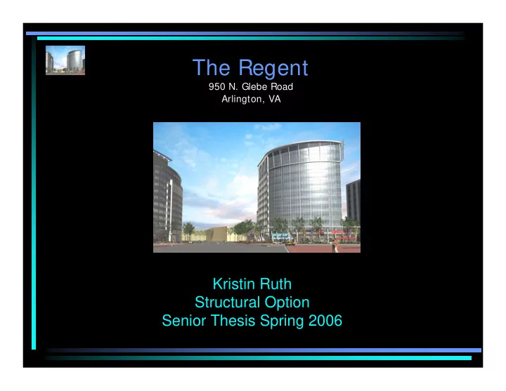
950 N. Glebe Road Arlington, VA
The Regent 950 N. Glebe Road Arlington, VA Kristin Ruth - - PowerPoint PPT Presentation
The Regent 950 N. Glebe Road Arlington, VA Kristin Ruth Structural Option Senior Thesis Spring 2006 Presentation Outline Introduction to The Regent Overview of the Existing Structural System Design Proposal Summary and Design
950 N. Glebe Road Arlington, VA
– 12 stories above grade - 265,243 SF
– 3 levels of parking below grade - 158,889 SF – Office levels are open floor plans with a typical central core – Height ≈ 180 FT
– $32,000,000 – Final completion 9-5-06
Lobby Eastern Elevation Cooper Carry Architects Cooper Carry Architects
grade) – Cast-in-place concrete columns – Columns on a 30’ x 30’ grid – Flat slabs with drop panels
– Long-span (46’/30’) composite steel beams @ 10’ o.c. with 3.25” lightweight slab on 3” composite metal deck – Bay sizes: 30’ x 30’ and 46’ x 30’ – Typical beam and girder sizes: W18’s, W16’s, and W21’s – Typical column sizes: W14’s
Composite Beam Floor System
System – N/S – (2) Braced frames
the building
– E/W – (3) Braced frames
the building
– Square spread footings – Sizes ranging from 4’ x 4’ to 9’ x 9’
Braced Frame
– Gravity: CIP concrete system using wide-module joists – Lateral: Shearwalls
– IBC 2000 – ASCE 7-02 – Live Loads reduced where applicable
JOIST KEY EXTERIOR JOISTS INTERIOR JOISTS
N
Interior Joists (30’ Span) Exterior Joists (46’ Span)
@ 6" O.C. 16" 8" 0.75" CLEAR 1 - #6 #3 STIRRUPS 9 - #5 48" 0.75" CLEAR 4.5"
+ n
M φ
− n
M φ
n
V φ
n
V φ
+ n
M φ
− n
M φ
n
V φ
# 3 S T IR R U P S 2 4 " 0 .7 5 " C L E A R 8 " @ 1 2 " O .C . 2 - # 1 0 4 8 " 0 .7 5 " C L E A R 9 - # 5 4 .5 "
40” Forms 8” ribs 4.5” Slab 24” Joist Depth Concrete System Floor Depth = 28.5” Steel System Floor Depth = 24.25” 40” Forms 8” ribs 4.5” Slab 16” Joist Depth Concrete System Floor Depth = 20.5” Steel System Floor Depth = 22.25”
GIRDER KEY EXTERIOR GIRDER INTERIOR GIRDER
N
Beff = 90" 41 2" 24" 24" #5 STIRRUPS @ 4" O.C. 1.5" CLEAR 1.5" CLEAR 1.5" CLEAR 12 - #9 8 - #9 #4 LONGITUDINAL REINFORCEMENT @ 12" SPACING
Beff = 27" 41 2" 24" 16" #4 STIRRUPS @ 5" O.C. #4 LONGITUDINAL REINFORCEMENT @ 12" SPACING 6 - #8 8 - #8 1.5" CLEAR 1.5" CLEAR 1.5" CLEAR
46' 43' 30'
24" x 28.5" 16" x 28.5"
30'
16" x 28.5" 24" D EEP RIB + 4.5" SLAB 24" x 28.5" (TYP.) 40" FO R M S + 8" R IBS @ 48" O .C. 24" DEEP R IB + 4.5" SLAB @ 48" O .C . 40" FO RM S + 8" R IBS
40" FO R M S + 8" R IBS @ 48" O .C . 16" D EEP R IB 4.5" SLAB
30' 46' 43'
24"
EXTERIOR GIRDER EXTERIOR COLUMN EXTERIOR JOISTS
4.5" SLAB EXTERIOR JOIST WEB (BEYOND)
24"
INTERIOR JOIST WEB (BEYOND) INTERIOR GIRDER
24" 4.5" SLAB 16"
INTERIOR COLUMN (BEYOND)
– Levels 1-5 – Levels 6-9 – Levels 10-12
C-3 C-4 C-5 C-6 C-7 C-8 C-9 C.3-11 D.8-10.8 F-7 F.1-10 F.7-9.2 H-8 SW 1 SW 2 SW 3 SW 4 SW 5 E-5 E-9 E-8.1 E-7 E-6.1 E-4 E-3 F-3 F-4 F-5 F-6.1 F-8.1 F-9 H-6 H-5 G.8-4 G.6-3 H-7
24" x 24" 30" x 30" 36" x 36" 18" x 18"
COLUMN KEY
N
C-4 C-5 C-6 C-7 C-8 C-9 C.3-11 D.8-10.8 F.7-9.2 F.1-10 H-8 SW 1 SW 2 SW 3 SW 4 SW 5 G.8-4 H-5 F-4 F-5 E-4 E-5 H-6 F-6.1 E-6.1 E-9 E-8.1 E-7 F-7 F-8.1 F-9 H-7
N
24" x 24" 30" x 30" 36" x 36" 18" x 18"
COLUMN KEY
C-5 C-6 C-7 C-8 C-9 C.3-11 D.8-10.8 F.1-10 F.7-9.2 H-8 SW 1 SW 2 SW 3 SW 4 SW 5 H-5 F-5 E-5 H-6 F-6.1 E-6.1 E-9 E-8.1 E-7 F-7 F-8.1 F-9 H-7
N
24" x 24" 30" x 30" 36" x 36" 18" x 18"
COLUMN KEY
C-3 C-4 C-5 C-6 C-7 C-8 C-9 C.3-11 D.8-10.8 F-7 F.1-10 F.7-9.2 H-8 SW 1 SW 2 SW 3 SW 4 SW 5 E-5 E-9 E-8.1 E-7 E-6.1 E-4 E-3 F-3 F-4 F-5 F-6.1 F-8.1 F-9 H-6 H-5 G.8-4 G.6-3 H-7
N
30’
Level 1 Level 2 Level 3 Level 4 Level 5 Level 6 Level 7 Level 8 Level 9 Level 10 Level 11 Level 12 ROOF 18' 13' 13' 13' 13' 13' 13' 13' 13' 13' 13' 32'-9" BOUNDARY ELEMENT (TYP.) 8" THICK SHEARWALL (TYP.) (2) CURTAINS OF #4 @ 18" O.C. E.W. (TYP.) 30'
C-3 C-4 C-5 C-6 C-7 C-8 C-9 C.3-11 D.8-10.8 F-7 F.1-10 F.7-9.2 H-8 SW 1 SW 2 SW 3 SW 4 SW 5 E-5
E-9
E-8.1
E-7
E-6.1 E-4 E-3 F-3 F-4 F-5 F-6.1 F-8.1 F-9 H-6 H-5 G.8-4 G.6-3 H-7
24" x 24" 30" x 30" 36" x 36" 18" x 18"
COLUMN KEY
N
8’ x 8’ x 38”
9.5’ x 9.5’ x 45”
9’ x 9’ x 50”
10.5’ x 10.5’ x 51”
$6,498 $238,328 $457,297 $0 $9,943 $149,865 Shoring/Reshoring $365 $11,484 $8,534 Shearwalls $625 $27,330 $24,756 Columns $965 $58,946 $48,707 Girders $4,543 $130,625 $225,435 Joists/Slab Equipment Labor Material Concrete Total Cost
$8,836 $32,692 $340,976 $659 $1,149 $22,447 Braced Members $631 $964 $74,396 Columns $4,937 $9,998 $160,851 Beams $728 $10,428 $41,468 Metal Deck $1,881 $10,153 $41,814 Slab on Deck Equipment Labor Material Steel Total Cost
$1,433 $3 $464 $966 E-9 (Steel) $2,289 $5 $701 $1,583 E-9 (Concrete) $2,319 $5 $722 $1,592 E-7 (Steel) $2,921 $6 $863 $2,052 E-7 (Concrete) Equip. Labor Material Total Cost Cost Footing
≈$600 difference ≈$850 difference
18-36” SQ W14’s Column Sizes 119/95 PSF 46 PSF Typical Floor System Weight Interior Bay – 16” Exterior Bay – 8” Interior Bay – 14.25” Exterior Bay – 12.25” Allowable Depth for Mechanical System 9.5’ x 9.5’ x 45” 8’ x 8’ x 38” Foundation Size for Gravity Only Column 10.5’ x 10.5’ x 50” 9’ x 9’ x 50” Foundation Size for Lateral Resisting and Gravity Column $2,289 $1,433 Cost of Foundation for Gravity Only Column $2,921 $2,319 Cost of Foundation for Lateral Resisting and Gravity Column 58 days 24 days Typical Floor Schedule $6,498 $8,836 Equipment $238,328 $32,692 Labor $457,297 $340,976 Material $702,123 $382,504 Cost of Typical Floor Interior Bay – 9’ Exterior Bay – 8’-8” Interior Bay – 9’ Exterior Bay – 9’ Floor to Ceiling Height 13’ 13’ Floor to Floor Height 28.5” (46’ span) 20.5” (30’ span) 24.25” (46’ span) 22.25” (30’ span) Floor System Depth CIP Concrete System Steel System
– Cheaper material and labor costs – Significantly shorter schedule (24 days/floor vs. 58 days/floor) – Thinner floor depth to accommodate the mechanical system layout and floor to ceiling height goals – Lighter system (46 PSF vs. ≈100 PSF) – Smaller foundations (by 1.5’ in each square dimension)
– Cheaper construction equipment costs – Interior bay has thinner floor system depth and greater allowable depth for the mechanical system
– Steve Sanko – Structural Design Group, Ltd.
– Katie Peterschmidt – Cooper Carry Architects – Lauren Schlather – Cooper Carry Architects
– Kevin Gunthert – JBG Owner Representative
–
–
–
–
– Paul Bowers