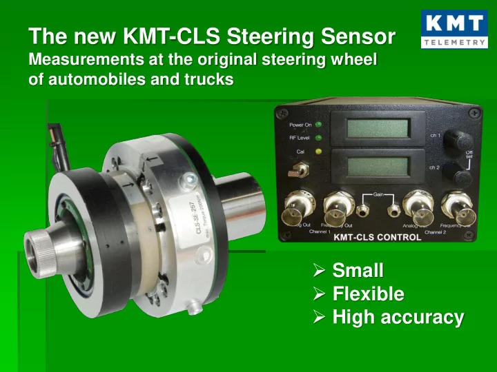
The new KMT-CLS Steering Sensor Measurements at the original - - PowerPoint PPT Presentation

the new kmt cls steering sensor
SMART_READER_LITE
LIVE PREVIEW

The new KMT-CLS Steering Sensor Measurements at the original - - PowerPoint PPT Presentation

The new KMT-CLS Steering Sensor Measurements at the original steering wheel of automobiles and trucks Small Flexible High accuracy Structure Development targets Configuration Installation Measurement technique


slide-1
SLIDE 1
  • Small
  • Flexible
  • High accuracy

The new KMT-CLS Steering Sensor

Measurements at the original steering wheel

  • f automobiles and trucks
slide-2
SLIDE 2
  • Development targets
  • Configuration
  • Installation
  • Measurement technique
  • Security
  • Conclusion

Structure

slide-3
SLIDE 3
  • 1. Development targets
slide-4
SLIDE 4
  • Maintained of the full functionality of the

standard steering wheel

  • Easy for mounting
  • Minimum effects on measurement
  • High accuracy
  • 1. Development targets
slide-5
SLIDE 5
  • 2. Configuration:
  • A modular solution!
  • Easy for mounting
slide-6
SLIDE 6
  • 2. Configuration :

An integrated solution!

  • Tight design
  • Easy to mount
  • Flexible

application

slide-7
SLIDE 7
  • 3. Installation:

Adapter

Adapter we can deliver: Either blank adapter for manufacturing the special toothing by yourself or by ourself  then we need exactly drawings

slide-8
SLIDE 8
  • 3. Installation :

Through connection

At the soldering pads you can transfer up to 6 signals e.g. :

  • power supply
  • Airbag
  • Lin bus

The contacts you can use up to 4 Ampere

Soldering pads at the upper side Soldering pads at the lower side

slide-9
SLIDE 9
  • 3. Installation :

Mounting Steering Column

Fit the adapter

slide-10
SLIDE 10
  • 3. Installation :

Mounting Sensor

Fit the sensor and tighten the central screw

slide-11
SLIDE 11
  • 3. Installation :

Mounting Steering adapter

Fit the adapter and tighten the screws

slide-12
SLIDE 12
  • 3. Installation :

Mounting angle encoder

Fit the angle encoder and tighten the screws Fixing of the torque bearing

slide-13
SLIDE 13
  • 3. Installation :

Mounting Steering wheel

Tighten the steering wheel and the central screws Mounting of the impact plate incl. Airbag Ready for take off!

slide-14
SLIDE 14
  • 4. Measuring: What kind of technique?

Steering torque:

Sensor integrated strain gage application: temperature compensated Measurement range: Nm 100 or 200 (choose when you order) Accuracy: % FS 0,2 Bandwidth: DC ... 800 Hz Direction of rotation: positive torque clockwise Temperature drift: max. 0.004% FS/°K

Angle sensor:

Sensor type: incremental magnetic sensor Angle resolution: 0.04° (8800 steps/360°)

slide-15
SLIDE 15
  • 4. Measuring: The Control Unit

Common

Dimensions:

  • ca. 80mm x 105mm x 185mm

Weight: 1,15 kg Temperature range:

  • 20°C ... + 80°C

Power supply: 9 ... 36 V/DC

slide-16
SLIDE 16
  • 4. Measuring: CAN-Bus Interface

Electrical interface: ISO/DIN 11898 incl. galvanic isolation Configuration: at CAN by using CCP-protocols, the identification is raised by serial number Baud rate: 10 kBaud ... 1 MBaud configurable by software Identifier: 11 bit oder 29 bit free configurable Message configuration: free configurable Update rate:

  • max. 5000 Hz, divisible be configurable, integer factor

Torque range: ± 100 Nm or ± 200 Nm depending of the type Torque resolution: 16 bit (0,003 Nm or 0,006 Nm) Rotation angle range: ± 1340° Rotation angle resolution: 16 bit : 0,04° (8800 steps/360°) Rotation speed: ± 1000°/sec Rotation speed resolution: 16 bit

slide-17
SLIDE 17
  • 4. Measuring: Analogue Outputs

Output voltage: ± 10 V Analogue offset balance: by rotary potentiometer at the front plate Bandwidth: 0 ... 800 Hz Torque range: ± 100 Nm or ± 200 Nm as the type may be Torque resolution: 12 bit (0,049 Nm or 0,098 Nm as the type may be) Rotation angle channel: ± 1000° (= ± 10 V) Rotation angle resolution: 0,65°

Autozero Button

Activate only CAN Interface Not active for analog output!

Rotation Angle Display (degrees) Steering Torque Display (Nm) Analog Offset Trim for Steering Torque Analog Offset Trim For Steering Angle Analogue output for steering torque Frequency output for steering torque Analogue output for steering angle Out off function!

Only for factory setting!

slide-18
SLIDE 18
  • 4. Measuring: What kind of technique?

Frequence output for torque

Type: 5 V TTL - rectangle signal Frequency range: 10000 Hz ± 5000 Hz 5000 Hz = - 100 Nm or - 200 Nm 10000 Hz = 0 Nm 15000 Hz = + 100 Nm or + 200 Nm

Digital display

Torque display: ± 100 Nm or ± 200 Nm for direct reading Torque display resolution: 0,1 Nm Rotation angle display: ± 1000° for direct reading Rotation angle display resolution: 1°

slide-19
SLIDE 19
  • 4. Measuring: Configuration
slide-20
SLIDE 20
  • 5. Security
  • Airbag will be full in function
  • Test driver will not be influenced by the measuring
  • All functions of the standard steering wheel you can

use without constrictions

  • Mechanical fracture torque > 500 Nm
  • Additional mechanical protection against breakage

is integrated

slide-21
SLIDE 21
  • 6. Conclusion
  • Very fast integration in a test vehicle
  • You can use the complete functionality of the standard

steering wheel

  • You can use the CLS in nearly all kinds of vehicles

(cars, trucks, tractors, military …)

  • Optimal signal resolution
  • Minimum effects on measurement

The new steering sensor – a fantastic solution!

slide-22
SLIDE 22

Thank you for your attention!

KMT- Kraus Messtechnik GmbH Martin Kraus – Sales Manager Gewerbering 9 D-83624 Otterfing - Germany

  • Tel. +49-8024-48737

Fax +49-8024-5532 Email: info@kmt-telemety.com Web: www.kmt-telemetry.com