the effect of number of fabric on cfrp fabric hybrid
play

THE EFFECT OF NUMBER OF FABRIC ON CFRP-FABRIC HYBRID COMPOSITE - PDF document

18 TH INTERNATIONAL CONFERENCE ON COMPOSITE MATERIALS THE EFFECT OF NUMBER OF FABRIC ON CFRP-FABRIC HYBRID COMPOSITE IMPACT SHIELD PERFORMANCE J. B. Moon 1 , G. S. Son 1 , Y. R. Park 1 , C. G. Kim 1 * 1 Division of Aerospace Engineering, School of


  1. 18 TH INTERNATIONAL CONFERENCE ON COMPOSITE MATERIALS THE EFFECT OF NUMBER OF FABRIC ON CFRP-FABRIC HYBRID COMPOSITE IMPACT SHIELD PERFORMANCE J. B. Moon 1 , G. S. Son 1 , Y. R. Park 1 , C. G. Kim 1 * 1 Division of Aerospace Engineering, School of Mechanical, Aerospace and System Engineering, Korea Advanced Institute of Science and Technology, Daejeon, Korea * Corresponding author(cgkim@kaist.ac.kr) Keywords : LEO space, MMOD, hypervelocity impact, hybrid shield, composite 1 Introduction 2.1 Concept of Shield Low earth orbit (LEO) which is 200 km to 6400 km The hybrid sandwich shielding system consists of altitude has many spacecrafts. There are many harsh two bumper plates and one intermediate fabric as environmental factors which can degrade material shown in Fig.1. The first bumper is made up of properties and damage the space structure. The main carbon fiber reinforced plastic (CFRP) which has constituents which can degrade the material good energy absorbing rate and light weight. And properties of composites are high vacuum, atomic the Kevlar fabric is added as interlayer with oxygen(AO), ultra-violet light(UV light) and unrestrained inplane boundary condition. Finally the thermal cycling. Another harsh environmental factor rear plate is made up of polymer plate which is is micro-meteoroid and orbital debris(MMOD). easily penetrated before the failure of Kevlar. MMOD is different from the previous 4 constituents. It does not contribute to the erosion of polymer Interlayer Gap materials. However, it occasionally collides with Rear plate spacecraft and damages the spacecraft severely. Hypervelocity impact with orbital debris and micro- meteoroids is highlighted as a severe threat to spacecraft due to their tremendously high velocity (5~70 km/s). Even with their small size, MMOD can cause critical damages to spacecraft when it is impacted and micrometeoroids and orbital debris 1 st Bumper plate (MMOD). These impacts can cause the degradation of the function of spacecraft, mission failure and Fig.1. Schematic of CFRP-Kevlar hybrid shield. 
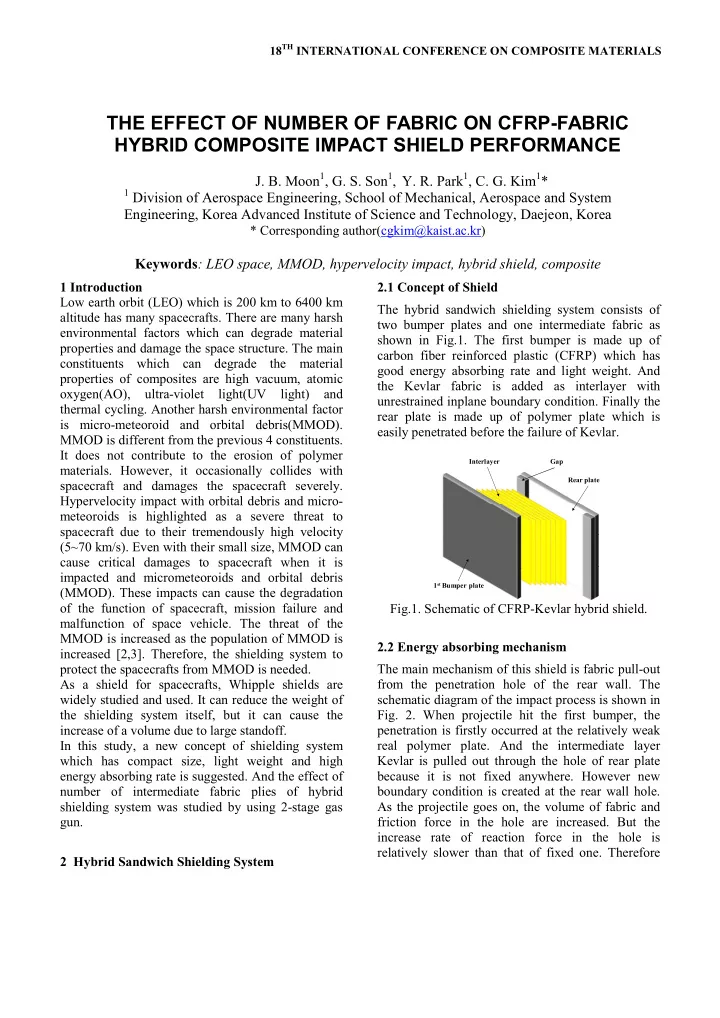
malfunction of space vehicle. The threat of the MMOD is increased as the population of MMOD is 2.2 Energy absorbing mechanism increased [2,3]. Therefore, the shielding system to protect the spacecrafts from MMOD is needed. The main mechanism of this shield is fabric pull-out As a shield for spacecrafts, Whipple shields are from the penetration hole of the rear wall. The schematic diagram of the impact process is shown in widely studied and used. It can reduce the weight of the shielding system itself, but it can cause the Fig. 2. When projectile hit the first bumper, the increase of a volume due to large standoff. penetration is firstly occurred at the relatively weak In this study, a new concept of shielding system real polymer plate. And the intermediate layer which has compact size, light weight and high Kevlar is pulled out through the hole of rear plate energy absorbing rate is suggested. And the effect of because it is not fixed anywhere. However new number of intermediate fabric plies of hybrid boundary condition is created at the rear wall hole. shielding system was studied by using 2-stage gas As the projectile goes on, the volume of fabric and friction force in the hole are increased. But the gun. increase rate of reaction force in the hole is relatively slower than that of fixed one. Therefore 2 Hybrid Sandwich Shielding System

  2. the energy absorbing occurs for much long time and the total absorbed energy is increased. Fabric with free boundary Friction force Projectile (a) Photo of 2 stage gas gun. Fabric pull-out with projectile 40 bar 130 bar Fig.2. Energy absorbing process of hybrid shield Reservoir Main Ar He controller cylinder (fabric pull-out mechanism). Sealing O-ring Launch 1 st diaphragm Pump Projectile tube tube Compressor 3 Experiment 3.1 Specimen preparation Plunger Plunger Lance 2 nd diaphragm Piston Cylinder Same front and rear bumper plate were used during (b) Schematic picture of 2 stage gas gun. experiment. The 1.8mm CFRP was prepared. It was Fig.3. 2-stage light gas gun. made up of CU125NS with stacking sequence of [0/ ± 45/90] 2s . And the 2mm poly methylmetaacrylate 3.3 Velocity measurement and calculation of (PMMA) was used as rear wall. The Kevlar KM2 energy absorption was used as interlayer. And 3 different number of ply were used to verify the effect of number of The velocity before and after impact were measured to calculate the difference in the kinetic energy and interlayer plies. finally determine the absorbed impact energy by the Table 1. Description of specimen structure. Negligible factors such as the heat produced from friction during impact, and acoustic Intermediate 1 st bumper Denotation Rear plate energy were discarded and Eq. 1 was used. layer CFRP Kevlar KM2 PMMA CKPA4 (1.8mm) 4 plies (2mm) (1) CFRP Kevlar KM2 PMMA CKPA6 (1.8mm) 6 plies (2mm) In the above equation, m is the mass of the projectile, V initial is the projectile velocity before impact, and CFRP Kevlar KM2 PMMA CKPA8 V residual is the velocity after impact. E air is the energy (1.8mm) 8 plies (2mm) loss due to the air since the projectile is not passing through vacuum but the atmosphere of 1 atm. E air 3.2 Hypervelocity impact simulation equipment was determined experimentally, and the result showed that depending on the initial projectile 2-stage gas gun was used to simulate the velocity it was linear. E air was concisely described as hypervelocity impact with space debris. Fig. 3 shows Eq. 2. the picture and the schematic diagram of 2-stage gas gun. The 5.56mm diameter spherical aluminum alloy (Al2017) ball was used as a projectile. The weight of aluminum ball is 0.25 ±0.001g. The (2) aluminum projectile was launched with average 2 chronographs were employed to measure the initial velocity of 1±0.05 km/s by using the gas gun. velocity and velocity after impact. The chronograph

  3. PAPER TITLE can measure up to 2km/s, and the 2 devices were energy absorbing rate of the hybrid composite shield. installed before and after the target fixture. Table 2 shows the shield energy absorbing rate A stainless steel case was manufactured and set with CKPA with different number of fabric. It shows that a 4 edge fixed constraint condition as shown in Fig. the all the CKPA had an energy absorption rate 4. This set up was then installed on the target fixture higher than that of the individual components sum between the 2 chronographs as shown in Fig. 4. The by about 8.91%, 7.92% and 4.19% for CKPA8, exposed specimen area during the impact test is CKPA6 and CKPA4 respectively. This shows that 100×100mm. by using unrestrained boundary added fabric, a new energy absorbing mechanism occurred. And it needed to have enough number of fabrics as intermediate layer. Table 2. Energy absorbing rate of CKPA hybrid composite shield with different number of fabric plies and sum of individual component Individual component Hybrid type CFRP KM2 PMMA Sum Fig. 4. Target fixture. 78.12J CKPA8 39.80J 10.38J 21.55J 71.73J (8.91%) 75.09J 4 Results and discussion CKPA6 39.80J 7.79J 21.55J 69.14J (7.92%) 4.1 Hypervelocity impact test result 69.45J CKPA4 39.80J 5.19J 21.55J 66.54J Fig. 5 shows the energy absorbing rates of CKPA8, (4.19%) CKPA6, and CKPA4. As can be seen in the figure, CKPA8 and CKPA6 shows similar energy absorbing 4.2 Penetration shape of hybrid composite shield rates. But the interlayer plies of fabric was smaller than 4 layers, the energy absorbing rate was The failure mode around the penetration hole for the decreased. CKPA design using the PMMA rear plate is shown in Fig. 6. 100 80 Absorbed energy (J) 60 40 CKPA8 CKPA6 Fabric pull out CKPA4 20 Deformed fabric 0 920 960 1000 1040 1080 1120 Velocity (m/s) Fig. 6. Fracture shape of hybrid CFRP_Kevlar_ Fig. 5. Absorbed energy of CKPA8, CKPA6 and MMA shield (fabric pull-out and deformed CKPA4. fabrics). The individual components energy absorbing rate The backside view image shows that a penetration was calculated. This was then compared to the hole of about diameter 9mm occurred in the PMMA 3

Download Presentation
Download Policy: The content available on the website is offered to you 'AS IS' for your personal information and use only. It cannot be commercialized, licensed, or distributed on other websites without prior consent from the author. To download a presentation, simply click this link. If you encounter any difficulties during the download process, it's possible that the publisher has removed the file from their server.

Recommend


More recommend