
SLIDE 1
Technical presentation of the Bernoulli Filter
1
- 1. Introduction
Technical presentation of the Bernoulli Filter 1. Introduction Many - - PDF document
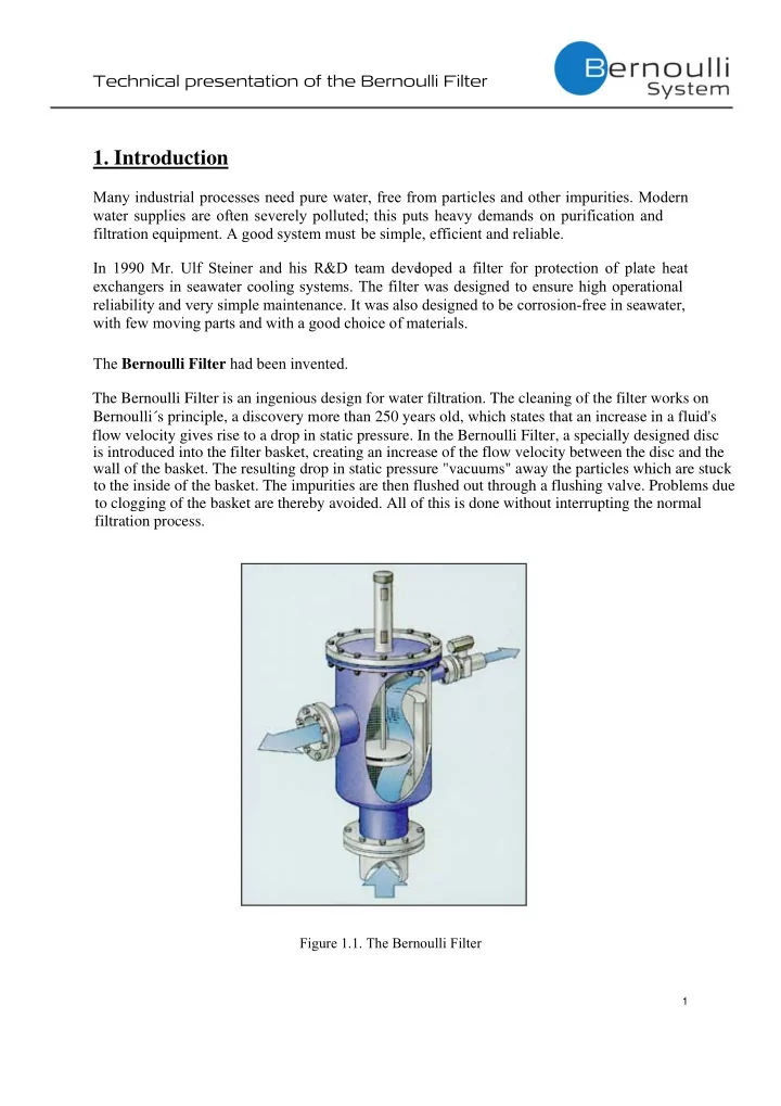
Technical presentation of the Bernoulli Filter 1. Introduction Many industrial processes need pure water, free from particles and other impurities. Modern water supplies are often severely polluted; this puts heavy demands on purification and
1
2
3
4
2 2 1 2 1 1 2 2 2 2 1 1 2 2 1 1
2 1
2 2 1 1 2 1
5
6
7
8
9
10
11