Tanks Essentials Organic Liquid Above-Ground Storage Tank Basics - - PowerPoint PPT Presentation

tanks essentials
SMART_READER_LITE
LIVE PREVIEW

Tanks Essentials Organic Liquid Above-Ground Storage Tank Basics - - PowerPoint PPT Presentation

Tanks Essentials Organic Liquid Above-Ground Storage Tank Basics Jim Miller, P.E. Senior Air Quality Engineer (512) 297-6448 Bart Leininger, P.E. Principal Ashworth Leininger Group Camarillo, CA Special Note: Credit for the tank design


slide-1
SLIDE 1

Page 1 Tanks Essentials 3/31/18
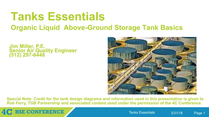
Tanks Essentials

Organic Liquid Above-Ground Storage Tank Basics

Bart Leininger, P.E. Principal Ashworth Leininger Group Camarillo, CA

Jim Miller, P.E. Senior Air Quality Engineer (512) 297-6448

Special Note: Credit for the tank design diagrams and information used in this presentation is given to Rob Ferry, TGB Partnership and associated content used under the permission of the 4C Conference.

slide-2
SLIDE 2

Page 2 Tanks Essentials 3/31/18

Objectives

  • Exposure to Tank Design Parameters
  • Understand Source Emissions Driving Forces and Calculation Basics
  • Evaluate Standard Practices for Emission Rate Determination
  • Introduction to Federal Regulatory Requirements
slide-3
SLIDE 3

Page 3 Tanks Essentials 3/31/18

Tank Categories

API 650

  • 0 to 2.5 psig, “atmospheric tanks”

API 620

  • Up to 15 psig, “low-pressure tanks”

ASME Boiler and Pressure Vessel Code, Section 8

  • Above 15 psig, “pressure vessels”
slide-4
SLIDE 4

Page 4 Tanks Essentials 3/31/18

Tank Design

  • Types of Above-Ground Organic Liquid Storage Tanks
  • Fixed-roof, IFR, EFR, Domed EFR
  • Types of Floating Roofs
  • IFR/EFR, bolted/welded, contact/noncontact
  • Floating Roof Design Details
  • Deck Seams, Rim Seals, Fittings
slide-5
SLIDE 5

Page 5 Tanks Essentials 3/31/18

Types of Above-Ground Storage Tanks

  • Fixed-roof
  • Fixed roof at the top of the shell; no floating roof
  • Internal floating roof (IFR)
  • Fixed roof and a light-duty floating roof
  • External floating roof (EFR)
  • Open top (no fixed roof), with a floating roof
  • Covered (Domed) external floating roof
  • Fixed roof and an external-type floating roof
slide-6
SLIDE 6

Page 6 Tanks Essentials 3/31/18

Fixed-Roof Tanks

  • No floating roof
  • Liquid surface is free to evaporate into the headspace
  • Typically low-profile cone roof supported with columns
  • Requires interior supports, frangible joint
  • Vented to the atmosphere
  • Open vents (gooseneck) or P/V breather vents
slide-7
SLIDE 7

Page 7 Tanks Essentials 3/31/18

Fixed-Roof Tanks

slide-8
SLIDE 8

Page 8 Tanks Essentials 3/31/18

Fixed-Roof Tank Driving Forces for Emissions: Working Losses

slide-9
SLIDE 9

Page 9 Tanks Essentials 3/31/18

Fixed-Roof Tank Driving Forces for Emissions: Standing Losses

slide-10
SLIDE 10

Page 10 Tanks Essentials 3/31/18

Fixed-Roof Tank Failures

slide-11
SLIDE 11

Page 11 Tanks Essentials 3/31/18

Fixed-Roof Tank Failures

slide-12
SLIDE 12

Page 12 Tanks Essentials 3/31/18

Fixed-Roof Tank Failures

slide-13
SLIDE 13

Page 13 Tanks Essentials 3/31/18

Fixed-Roof Tank Failures

slide-14
SLIDE 14

Page 14 Tanks Essentials 3/31/18

Internal Floating-Roof Tanks (IFRTs)

  • Floating roof covers the liquid surface
  • Greatly reducing free evaporation into the headspace
  • Fixed roof is freely vented
  • For maintaining vapors << LEL (unless gas blanketed)
  • Floating roof deck is lightweight, per API 650, App. H
  • Protection by the fixed roof allows lightweight design
  • Some vapors escape past the floating roof
  • At rim seals, deck fittings, & deck seams (if bolted)
slide-15
SLIDE 15

Page 15 Tanks Essentials 3/31/18

Internal Floating-Roof Tanks

slide-16
SLIDE 16

Page 16 Tanks Essentials 3/31/18

IFRT Summary

  • Deck construction can be lightweight
  • Short sleeves (housings) for deck support legs
  • Deck seams may be bolted (typ. for aluminum)
  • Fixed roof may require support columns
  • Which penetrate the deck, creating paths for emissions
  • Wind is not a factor in emissions
  • Vapors escape past the floating roof independent of ambient wind speed, and

daily breathing results in enough air movement to carry vapors out of the tank

slide-17
SLIDE 17

Page 17 Tanks Essentials 3/31/18

External Floating-Roof Tanks (EFRTs)

  • Floating roof covers the liquid surface
  • Greatly reducing free evaporation
  • Fixed roof is subject to wind action
  • Tank shell provides a partial shield, but losses still wind driven
  • Floating roof deck is heavyweight, per API 650, App. C
  • Designed for external forces (e.g., snow, torrential rain)
  • Some vapors escape past the floating roof
  • At rim seals, deck fittings (but deck seams are welded)
slide-18
SLIDE 18

Page 18 Tanks Essentials 3/31/18

External Floating-Roof Tank

slide-19
SLIDE 19

Page 19 Tanks Essentials 3/31/18

EFRT Summary

  • Deck construction is heavyweight
  • Tall sleeves (housings) for deck support legs
  • Welded deck seams
  • No fixed roof; no support columns
  • Typically fewer deck penetrations than for an IFRT
  • Wind is a factor in emissions
  • The rate at which vapors escape past the floating roof is very sensitive to

ambient wind speed

  • Wind action offsets lower loss factors, fewer fittings
slide-20
SLIDE 20

Page 20 Tanks Essentials 3/31/18

Covered (Domed) External Floating-Roof Tanks

  • Differs from IFRT in the type of floating roof
  • EFR-type deck, w/ welded deck seams, tall leg sleeves
  • Fixed roof is freely vented (as for IFRT)
  • Typically an aluminum dome over an EFRT
  • Particularly for retrofit applications, where a dome can be installed in-service
  • Could be a steel cone roof, but this would typically involve installing out-of-

service, roof support columns

slide-21
SLIDE 21

Page 21 Tanks Essentials 3/31/18

Covered (Domed) External Floating-Roof Tank

slide-22
SLIDE 22

Page 22 Tanks Essentials 3/31/18

Domed External Floating-Roof Tank Summary

  • Deck construction is heavyweight
  • Tall sleeves (housings) for deck support legs
  • Welded deck seams
  • Typically with dome roof; no columns
  • Means typically fewer deck penetrations than for an IFRT
  • Wind is not a factor in emissions
  • Lower loss factors, fewer fittings, and not subject to wind action – lowest emitting

type of construction.

slide-23
SLIDE 23

Page 23 Tanks Essentials 3/31/18

Floating Roof Tank Driving Forces for Emissions: Working Losses

slide-24
SLIDE 24

Page 24 Tanks Essentials 3/31/18

Floating Roof Tank Driving Forces for Emissions: Standing Losses

slide-25
SLIDE 25

Page 25 Tanks Essentials 3/31/18

Floating Roof Features

  • Emissions sources
  • Withdrawals
  • Deck Seams (bolted decks only)
  • Rim Seals
  • Deck Fittings
  • Controls
  • Rim Seals
  • Deck Fittings
slide-26
SLIDE 26

Page 26 Tanks Essentials 3/31/18

Types of Floating Roof Decks

slide-27
SLIDE 27

Page 27 Tanks Essentials 3/31/18

Floating Roof Cutaway

slide-28
SLIDE 28

Page 28 Tanks Essentials 3/31/18

Pan Deck

slide-29
SLIDE 29

Page 29 Tanks Essentials 3/31/18

Bulkheaded Deck

slide-30
SLIDE 30

Page 30 Tanks Essentials 3/31/18

Pontoon Deck

slide-31
SLIDE 31

Page 31 Tanks Essentials 3/31/18

Pontoon Deck

slide-32
SLIDE 32

Page 32 Tanks Essentials 3/31/18

Double-Deck

slide-33
SLIDE 33

Page 33 Tanks Essentials 3/31/18

Double Deck

slide-34
SLIDE 34

Page 34 Tanks Essentials 3/31/18

On-Floats Deck

  • aka skin & pontoon, or noncontact
slide-35
SLIDE 35

Page 35 Tanks Essentials 3/31/18

On-Floats Deck

  • aka skin & pontoon, or noncontact
slide-36
SLIDE 36

Page 36 Tanks Essentials 3/31/18

Sandwich Panel Deck

slide-37
SLIDE 37

Page 37 Tanks Essentials 3/31/18

Sandwich Panel Deck

slide-38
SLIDE 38

Page 38 Tanks Essentials 3/31/18

Floating Roof Considerations

  • Design:
  • External floating roofs per API 650, Appendix C
  • Internal floating roofs per API 650, Appendix H
  • Costs
  • Environmental
  • Fire Safety
slide-39
SLIDE 39

Page 39 Tanks Essentials 3/31/18

External Floating Roofs

  • Potentially more economical to initially construct versus IFR
  • But future costs may be unacceptable:
  • Problems associated with water intrusion
  • Drain lines pose maintenance problems
  • Snow load poses maintenance problems
  • Higher liquid surface temp = higher emissions
  • This is not presently accounted for in the emission factors, but an API study is seeking to

quantify this

slide-40
SLIDE 40

Page 40 Tanks Essentials 3/31/18

Floating Roof Considerations

  • Design:
  • External floating roofs per API 650, Appendix C
  • Internal floating roofs per API 650, Appendix H
  • Costs
  • Environmental
  • Fire Safety
slide-41
SLIDE 41

Page 41 Tanks Essentials 3/31/18

Rainwater Problems with an EFRT

slide-42
SLIDE 42

Page 42 Tanks Essentials 3/31/18

EFR Drain Line Problems

slide-43
SLIDE 43

Page 43 Tanks Essentials 3/31/18

Snow Problems with an EFRT

slide-44
SLIDE 44

Page 44 Tanks Essentials 3/31/18

Emissions Increased with an EFRT

slide-45
SLIDE 45

Page 45 Tanks Essentials 3/31/18

Fixed Roofs for Floating Roof Tanks

  • Steel cone roof
  • Typically column supported
  • Requires painting for maintenance
  • Retrofit installation requires out-of-service
  • Aluminum dome roof
  • Self-supporting (no interior columns)
  • No painting necessary
  • Retrofit installation may be done in-service
slide-46
SLIDE 46

Page 46 Tanks Essentials 3/31/18

Problems with Support Columns

  • Increased air emissions
  • Due to penetrations through the floating roof
  • May involve significant foundation costs
  • Soft soils may require piles under each column.
  • High corrosion potential/unable to inspect
  • Bottom corrosion & leaks are accelerated at columns
  • Interfere with secondary bottom installation
slide-47
SLIDE 47

Page 47 Tanks Essentials 3/31/18

Support Columns

slide-48
SLIDE 48

Page 48 Tanks Essentials 3/31/18

IFR Comparison

slide-49
SLIDE 49

Page 49 Tanks Essentials 3/31/18

Limitations for Pan-Type

  • Does not meet NFPA 30 criteria
  • Nor does the bulkheaded, as noted in the prior table - they do not have enclosed

flotation compartments

  • Does not provide redundant buoyancy
  • A single leak can flood the entire deck, whereas other designs still float with two

flooded compartments.

  • Is readily sunk by upsets or turbulence
  • Unsymmetrical loading may buckle the rim of the deck, allowing it to fold up like a

taco.

  • Foam system must be for full surface area.
slide-50
SLIDE 50

Page 50 Tanks Essentials 3/31/18

Floating Roof “Taco” Failure

slide-51
SLIDE 51

Page 51 Tanks Essentials 3/31/18

Costs of Steel IFRs

  • Higher than aluminum for initial installation
  • More loss of capacity than aluminum
  • Heavier material displaces more liquid
  • Doorsheet escalates replacement costs
  • The doorsheet itself involves additional construction
  • A hydrotest is required when complete
  • To test the integrity of the doorsheet, and
  • To stress relieve the doorsheet welds
slide-52
SLIDE 52

Page 52 Tanks Essentials 3/31/18

Comparison of Aluminum IFRs

  • Sandwich panel type:
  • More expensive than skin and pontoon,
  • More length of deck seams (higher emissions),
  • May require doorsheet/hydrotest to replace
  • If closed cell core, inherent safety concerns
  • Appendix H states that this type is “permitted however…enclosed spaces within a

module may result in undetectable combustible gas.”

  • This type, then, does not provide the safety implicit in H.4.1.7
slide-53
SLIDE 53

Page 53 Tanks Essentials 3/31/18

Comparison of Aluminum IFRs

  • Skin and pontoon type:
  • Least expensive,
  • Lower emissions than sandwich panel,
  • Replace without doorsheet or roof hole,
  • Foam system must be designed for full surface
  • Skin and pontoon type decks cost less than other types both initially and for replacement,

but if a foam system is required for fire protection the foam system will cost more for skin and pontoon aluminum than for steel pontoon or doubledeck.

slide-54
SLIDE 54

Page 54 Tanks Essentials 3/31/18

Aluminum Skin & Pontoon

  • If best, why are others even considered?
  • Seems to be clear choice from value engineering
  • Negative perceptions in the market:
  • Flexibility is disconcerting for personnel.
  • Reputation of poor service history.
  • The Question: Are they inherently flimsy,

OR have they been underdesigned?

slide-55
SLIDE 55

Page 55 Tanks Essentials 3/31/18

Aluminum Skin & Pontoon – Negative Perceptions

  • Flexibility is disconcerting for personnel.
  • Workers feel uneasy walking on it
  • Safe, but sensation like walking on a huge waterbed
  • A moot point in light of Confined Space Entry
  • Workmen generally not allowed to enter any IFRT
  • Reputation for poor service history.
  • API 650 Appendix H has had a design loophole.
  • Only required to support 500 pounds.
slide-56
SLIDE 56

Page 56 Tanks Essentials 3/31/18

API 650, Appendix H pre-Revision

  • Design standard for all IFRs
  • Allowed waiver of uniform live load
  • If equipped with deck drains
  • Only design load was then 500 pound load
  • As a result, some manufacturers use few legs
  • ‘Typical’ tributary area assumed for emission estimates is about 400 square feet per leg

(an area 40 ft x 10 ft)

slide-57
SLIDE 57

Page 57 Tanks Essentials 3/31/18

API 650, Appendix H post-Revision

  • All IFRs to support uniform live load:
  • Still 12.5 psf if no deck drains.
  • Now 5 psf with deck drains.
  • This translates to 2,000 lbs for a 400 sq.ft. area.
  • Most failures have had too few deck legs.
  • Legs on 40 ft spacing would now need 10 ft spacing, or
  • Support 4-times more load than previously.
slide-58
SLIDE 58

Page 58 Tanks Essentials 3/31/18

Aluminum Skin & Pontoon - Summary of Service History

  • Frequent failures occur with poor designs
  • Successful deck leg design has featured:
  • Limit on tributary area of about 200 square feet
  • Designed to support 1000 pounds {5 psf}
  • Designed for real world load conditions
  • (i.e., out-of-plumb, out-of-level, & subject to cyclic loads)
  • Properly designed skin & pontoon IFRs can last longer w/o major repairs

than the tank

slide-59
SLIDE 59

Page 59 Tanks Essentials 3/31/18

Summary of IFR Types

  • Steel pontoon and double deck:
  • Most durable, lowest emissions, best fire safety
  • Most expensive
  • Aluminum skin-and-pontoon:
  • Best value for many applications IF well made
  • Quality varies greatly
  • Higher emissions
  • Other designs:
  • May suit limited or specialized applications
slide-60
SLIDE 60

Page 60 Tanks Essentials 3/31/18

Floating Roof Features

  • Points of emissions from floating roofs
  • Deck seams (if bolted), rim seals, deck fittings
  • Types of devices to control emissions
  • Features of common rim seals and deck fitting controls
slide-61
SLIDE 61

Page 61 Tanks Essentials 3/31/18

Points of Emissions from Floating Roofs

  • Deck Seams
  • Contribute to emissions if bolted; but not if welded
  • Rim Seals
  • This is the closure device between the deck and tank
  • Deck Fittings
  • Only those features that open through the deck to the stored liquid are

considered to be deck fittings for emissions purposes

slide-62
SLIDE 62

Page 62 Tanks Essentials 3/31/18

Deck Seams – Sheet Construction

slide-63
SLIDE 63

Page 63 Tanks Essentials 3/31/18

Deck Seams – Panel Construction

slide-64
SLIDE 64

Page 64 Tanks Essentials 3/31/18

Rim Seals

slide-65
SLIDE 65

Page 65 Tanks Essentials 3/31/18

Rim Seal Vapor Space

slide-66
SLIDE 66

Page 66 Tanks Essentials 3/31/18

Rim Seal Emissions

slide-67
SLIDE 67

Page 67 Tanks Essentials 3/31/18

Types of Primary Rim Seals

  • Vapor-mounted:
  • Highest emissions - Fair service history
  • Liquid-mounted:
  • Lowest emissions - Poorest service history
  • Mechanical-shoe:
  • Fairly low emissions - Best service history
  • Note that, in California, a mechanical-shoe seal is considered a type of liquid-mounted

seal, rather than a separate category of rim seal.

slide-68
SLIDE 68

Page 68 Tanks Essentials 3/31/18

Vapor-Mounted Rim Seal

  • Bottom is not in contact with the liquid surface
  • Annular vapor space beneath the rim seal
  • Between the rim of the deck and the shell of the tank
  • Two common types:
  • Flexible-wiper (blade)
  • Continuous wiper blade around the rim of the deck
  • Resilient-filled type
  • A foam log within an elastomeric-coated fabric envelope
  • The envelope protects the foam core from liquid & abrasion
slide-69
SLIDE 69

Page 69 Tanks Essentials 3/31/18

Vapor-Mounted Rim Seal – Flexible-Wiper Type

slide-70
SLIDE 70

Page 70 Tanks Essentials 3/31/18

Vapor-Mounted Rim Seal – Resilient-Filled Type

slide-71
SLIDE 71

Page 71 Tanks Essentials 3/31/18

Liquid-Mounted Rim Seal

  • Bottom of the seal contacts the liquid surface
  • The rim vapor space is virtually eliminated
  • Resilient-filled design
  • Typically a foam log in an elastomeric-coated fabric
  • Differs from resilient-filled vapor-mounted rim seal in its position relative to

the liquid

  • i.e., whether or not the bottom of the seal contacts the liquid surface
slide-72
SLIDE 72

Page 72 Tanks Essentials 3/31/18

Liquid-Mounted Rim Seal

slide-73
SLIDE 73

Page 73 Tanks Essentials 3/31/18

Mechanical-Shoe Rim Seal

  • Metallic shoe - slides against the tank shell
  • A series of overlapping sheets form a ring inside the shell
  • Mechanical device - pushing the shoe outward
  • Regularly spaced devices hold the shoe against the shell
  • Primary seal fabric - to cover the annular space
  • An elastomeric-coated fabric closes the annular space between the metallic shoe

and the rim of the deck

  • In California, mechanical-shoe is considered a type of liquid-mounted seal,

rather than a separate category

slide-74
SLIDE 74

Page 74 Tanks Essentials 3/31/18

Mechanical-Shoe Rim Seal

slide-75
SLIDE 75

Page 75 Tanks Essentials 3/31/18

Strategies to Improve Rim Seal Effectiveness

  • Minimize gaps between rim seal and tank shell
  • Seek to keep the rim seal firmly against the tank shell
  • Minimize the rim space tributary to a gap
  • Fill the rim space or provide a baffle to isolate it
  • Provide secondary closure of the rim space
  • Equip the floating roof with a secondary rim seal
slide-76
SLIDE 76

Page 76 Tanks Essentials 3/31/18

Minimize Rim Seal Gaps

slide-77
SLIDE 77

Page 77 Tanks Essentials 3/31/18

Baffle-Type Controls

slide-78
SLIDE 78

Page 78 Tanks Essentials 3/31/18

Rim Seal Gaps – Mechanical-shoe Seal

slide-79
SLIDE 79

Page 79 Tanks Essentials 3/31/18

Eliminate the Rim Space (Filling It)

slide-80
SLIDE 80

Page 80 Tanks Essentials 3/31/18

Rim Seal Gaps – Liquid-mounted Seal

slide-81
SLIDE 81

Page 81 Tanks Essentials 3/31/18

Secondary Rim Seals

  • Purpose is to reduce emissions
  • Particularly effective for external floating roofs
  • Mounted above the primary seal
  • The secondary is the upper seal in a double seal system
  • May be added to any type of primary seal
  • Mounted sufficiently high to not interfere w/the primary
  • Generally results in loss of tank capacity
  • Particularly with internal floating roofs, where the fixed roof limits upward travel of

the floating roof

slide-82
SLIDE 82

Page 82 Tanks Essentials 3/31/18

Secondary Rim Seals – Rim-Mounted Secondary; Mechanical Shoe Primary

slide-83
SLIDE 83

Page 83 Tanks Essentials 3/31/18

Secondary Rim Seals – Shoe-Mounted Secondary; Mechanical Shoe Primary

slide-84
SLIDE 84

Page 84 Tanks Essentials 3/31/18

Secondary Rim Seals – Wiper Secondary; Log Seal Primary

slide-85
SLIDE 85

Page 85 Tanks Essentials 3/31/18

Secondary Rim Seals – Wiper Secondary; Wiper Primary

slide-86
SLIDE 86

Page 86 Tanks Essentials 3/31/18

Deck Fittings – Common Features

  • Only create emissions if through to liquid
  • Deck opening may be round or square
  • Shape of opening is a matter of fabricator preference
  • Bottom of opening (for most) extends below the liquid surface
  • Noncontact decks require a well extension or skirt
  • If for a penetration, deck cover must be loose
  • The cover must be allowed to slide for out-of-plumbness
slide-87
SLIDE 87

Page 87 Tanks Essentials 3/31/18

Deck Fittings

slide-88
SLIDE 88

Page 88 Tanks Essentials 3/31/18

Not Deck Fittings

slide-89
SLIDE 89

Page 89 Tanks Essentials 3/31/18

Deck Fittings

slide-90
SLIDE 90

Page 90 Tanks Essentials 3/31/18

Deck Fittings – Basic Categories

  • Small opening (nozzle or pipe sleeve) type
  • e.g., deck support legs, gauge hatches, deck drains.
  • Vent devices
  • Not required to extend below the liquid surface
  • Large opening (well) type
  • e.g., manways, gauge float wells, column wells, and vertical ladders
  • Guidepoles–aka gaugepoles, gaugepipes, etc.
  • Important enough to be a category unto themselves
slide-91
SLIDE 91

Page 91 Tanks Essentials 3/31/18

Deck Fittings – Support Legs

slide-92
SLIDE 92

Page 92 Tanks Essentials 3/31/18

Deck Support Legs – Control Options

slide-93
SLIDE 93

Page 93 Tanks Essentials 3/31/18

Sample Ports

slide-94
SLIDE 94

Page 94 Tanks Essentials 3/31/18

Effectiveness of Slit Fabric/Slotted Membrane

  • There is no apparent benefit to 90% closure at 0 mph wind
  • By comparison, emission factor for an uncontrolled slotted guidepole at 10

mph is 4200 lb-mol/yr

slide-95
SLIDE 95

Page 95 Tanks Essentials 3/31/18

Deck Drains

(that empty into stored liquid)

slide-96
SLIDE 96

Page 96 Tanks Essentials 3/31/18

Rim Space Vents

slide-97
SLIDE 97

Page 97 Tanks Essentials 3/31/18

Vacuum Breaker (Automatic Bleeder Vent)

slide-98
SLIDE 98

Page 98 Tanks Essentials 3/31/18

Vacuum Breaker (Automatic Bleeder Vent)

slide-99
SLIDE 99

Page 99 Tanks Essentials 3/31/18

Access Hatch (Manway)

slide-100
SLIDE 100

Page 100 Tanks Essentials 3/31/18

Gauge Float (Automatic Tank Gauge)

slide-101
SLIDE 101

Page 101 Tanks Essentials 3/31/18

Fixed Roof Support Column

slide-102
SLIDE 102

Page 102 Tanks Essentials 3/31/18

Fixed Roof Support Column

slide-103
SLIDE 103

Page 103 Tanks Essentials 3/31/18

Fixed Roof Support Column

slide-104
SLIDE 104

Page 104 Tanks Essentials 3/31/18

Fixed Roof Support Column

slide-105
SLIDE 105

Page 105 Tanks Essentials 3/31/18

Vertical Ladder

slide-106
SLIDE 106

Page 106 Tanks Essentials 3/31/18

Guidepoles

slide-107
SLIDE 107

Page 107 Tanks Essentials 3/31/18

Guidepole Functions

  • Anti-rotation devices
  • Sampling location
  • Level gauge location

To measure the level of the liquid in the tank

slide-108
SLIDE 108

Page 108 Tanks Essentials 3/31/18

Unslotted Guidepoles

slide-109
SLIDE 109

Page 109 Tanks Essentials 3/31/18

Slotted Guidepoles

slide-110
SLIDE 110

Page 110 Tanks Essentials 3/31/18

Function of Slots in a Guidepole

  • Allow bulk liquid to flow freely into the pole
  • To achieve accurate sampling
  • To achieve accurate level gauging
  • Avoid confined space entry
  • Definition of a slotted guidepole: (Per Generic MACT, 63 Subpart WW)
  • A guidepole or gaugepole that has slots or holes through the wall of the pole

[that] allow the stored liquid to flow into the pole at liquid levels above the lowest

  • perating level
slide-111
SLIDE 111

Page 111 Tanks Essentials 3/31/18

Unslotted Guidepole

slide-112
SLIDE 112

Page 112 Tanks Essentials 3/31/18

Unslotted Guidepole

slide-113
SLIDE 113

Page 113 Tanks Essentials 3/31/18

Unslotted Guidepole

slide-114
SLIDE 114

Page 114 Tanks Essentials 3/31/18

Slotted Guidepole

slide-115
SLIDE 115

Page 115 Tanks Essentials 3/31/18

Slotted Guidepole

slide-116
SLIDE 116

Page 116 Tanks Essentials 3/31/18

Slotted Guidepole

slide-117
SLIDE 117

Page 117 Tanks Essentials 3/31/18

Pole Float

slide-118
SLIDE 118

Page 118 Tanks Essentials 3/31/18

Pole Float

slide-119
SLIDE 119

Page 119 Tanks Essentials 3/31/18

Short Pole Float

slide-120
SLIDE 120

Page 120 Tanks Essentials 3/31/18

Pole Sleeve

slide-121
SLIDE 121

Page 121 Tanks Essentials 3/31/18

Flexible Enclosure (Accordion)

slide-122
SLIDE 122

Page 122 Tanks Essentials 3/31/18

Guidepole/Ladder Combination

slide-123
SLIDE 123

Page 123 Tanks Essentials 3/31/18

Guidepole/Ladder Combination

slide-124
SLIDE 124

Page 124 Tanks Essentials 3/31/18

Guidepole/Ladder Combination

slide-125
SLIDE 125

Page 125 Tanks Essentials 3/31/18

Estimating Storage Tank Air Emissions

slide-126
SLIDE 126

Page 126 Tanks Essentials 3/31/18

Brief History of Calculation Development

  • Data from testing for over 20 years
  • Sponsored by API, in cooperation with EPA
  • Published by both API and EPA
  • Chapter 19 of API’s MPMS
  • Section 7.1 of EPA’s AP-42
  • liquid in the tank
slide-127
SLIDE 127

Page 127 Tanks Essentials 3/31/18

Brief History of API Research

  • Pilot tank testing in the late 1970’s
  • Yielded useful results, such as effect of ambient wind
  • Not feasible for isolating components
  • Wind tunnel and bench scale tests
  • Testing of individual deck fittings and rim seals
  • Testing at various wind speeds
  • ‘Zero wind speed’: frequent air changes (not still air)
  • Bolted deck seams the most difficult to standardize
slide-128
SLIDE 128

Page 128 Tanks Essentials 3/31/18

API’s MPMS Chapter 19

Manual of Petroleum Measurement Standards Chapter 19 – Evaporative Loss Measurement

  • 19.1 Evaporative Loss from Fixed-Roof Tanks
  • 19.2 Evaporative Loss from Floating-Roof Tanks
  • 19.3 Loss Factor Certification Program
  • Parts A-E are test methods
  • Parts F-H are for administration of the tests
  • 19.4 Evaporative Loss Reference Information and Speciation Methodology

(Oct. 2012)

slide-129
SLIDE 129

Page 129 Tanks Essentials 3/31/18

EPA’s AP-42

Compilation of Air Pollutant Emission Factors

  • Volume I: Stationary Point and Area Sources
  • Contains emission factors for all sorts of sources
  • Section 7.1 – Organic Liquid Storage Tanks
  • Fifth Edition, Supplement D – September ’97
  • 2006 Revision added Floating Roof Landing Losses
  • But Landing Losses not in TANKS 4.09D
  • Most agencies reference AP-42 equations
slide-130
SLIDE 130

Page 130 Tanks Essentials 3/31/18

MPMS 19 versus AP-42 7.1

  • The loss factors and equations used are identical, with the following

exception:

  • Bolted deck seam loss factor
  • EPA reduced this factor by about 60% (0.14 vs 0.34) in response to data from testing in

the late 1990’s.

  • API has not changed from the earlier value of 0.34
  • Liquid surface temperature – no longer different
  • Had been different for floating-roof tanks, but the API method was reconciled to

the EPA method in the Oct 2012 revisions to API MPMS 19.2 and 19.4

  • Most agencies refer to emissions equations in AP-42
slide-131
SLIDE 131

Page 131 Tanks Essentials 3/31/18

Emissions Driving Forces Review

  • Losses due to liquid throughputs
  • Fixed-roof: working loss (filling)
  • Floating-roof: withdrawal loss (clingage)
  • Losses when tank is static
  • Fixed-roof: standing loss (breathing)
  • Floating-roof: standing loss
  • Due to vapors escaping past the rim seal and through deck fittings (and deck seams, if

bolted)

slide-132
SLIDE 132

Page 132 Tanks Essentials 3/31/18

Fixed-Roof Tank: Filling Loss

slide-133
SLIDE 133

Page 133 Tanks Essentials 3/31/18

Fixed-Roof Tank Filling (Working) Loss

Equation (1-35) for estimating working loss, LW: LW = N [ HLX (π/4) D2 ] KN KP WV KB

where N = turnover rate [turnovers/year] HLX = maximum liquid height [feet] D = tank diameter [feet] KN = working loss turnover (saturation) factor [dimensionless] KP = working loss product factor [dimensionless] (0.75 or 1) WV = stock vapor density [lb/ft3] KB = vent setting correction factor [dimensionless]

slide-134
SLIDE 134

Page 134 Tanks Essentials 3/31/18

Fixed-Roof Tank Saturation Factor

KN = working loss turnover (saturation) factor [dimensionless] For turnovers ≤36: KN = 1 For turnovers >36: KN = (180 + N)/6N Asymptotically approaches 0.167

slide-135
SLIDE 135

Page 135 Tanks Essentials 3/31/18

Fixed-Roof Tank Filling (Working) Loss

  • Stock vapor density, WV [lb/ft3] (Equation 1-21)

WV = MV PVA / (R TLA)

where:

  • MV = vapor molecular weight [lb/lb-mole]
  • R = the ideal gas constant (10.731 psia ft3/lb-mole °R)
  • PVA = vapor pressure at daily avg liquid surface temperature [psia]
  • TLA = daily average liquid surface temperature [°R]
slide-136
SLIDE 136

Page 136 Tanks Essentials 3/31/18

Fixed-Roof Tank Filling (Working) Loss

  • Vent setting correction factor, KB

(Eq 1-37)

(Only used if breather vent settings are greater than the typical ±0.3 psig)

KB = [(PI + PA) / KN – PVA] / (PBP + PA - PVA)

where:

  • PI = pressure of the vapor space at normal operating conditions [psig] (0 if

tank is atmospheric: not held at constant pres/vac)

  • PA = atmospheric pressure [psia]
  • KN = working loss turnover (saturation) factor [dimensionless]
  • PVA = vapor pressure at the daily average liquid surface temperature [psia]
  • PBP = breather vent pressure setting [psig]
slide-137
SLIDE 137

Page 137 Tanks Essentials 3/31/18

Fixed-Roof Tank Standing Losses

slide-138
SLIDE 138

Page 138 Tanks Essentials 3/31/18

Fixed-Roof Tank Standing (Breathing) Loss

Equation (1-4) for estimating standing loss, LS: LS = 365 KE (π/4 D2) HVO KS WV

where 365 = number of daily events per year [year -1] KE = vapor space expansion factor [dimensionless] (1-5, 1-7) D = tank diameter [feet] HVO = vapor space outage [feet] (1-15) KS = vented vapor saturation factor [dimensionless] (1-20) WV = stock vapor density [lb/ft3] (1-21)

slide-139
SLIDE 139

Page 139 Tanks Essentials 3/31/18

Fixed-Roof Tank Standing (Breathing) Loss

Equation (1-5) for estimating vapor space expansion factor for products with PV < 0.1 psia: KE = 0.0018 [0.72 (TAX − TAN) + 0.028 α I]

where TAX = daily maximum ambient temperature [°R] TAN = daily minimum ambient temperature [°R] α = tank paint solar absorptance [dimensionless] I = daily total solar insolation on a horizontal surface [Btu/(ft2 day)] 0.0018 = constant, [(°R)-1] 0.72 = constant [dimensionless] 0.028 = constant [(°R ft2 day)/Btu]

slide-140
SLIDE 140

Page 140 Tanks Essentials 3/31/18

Fixed-Roof Tank Standing (Breathing) Loss

Equation (1-7) for estimating vapor space expansion factor for products with PV > 0.1 psia: KE = Δ TV / TLA + (Δ PV - Δ PB) / (PA - PVA) > 0

where Δ TV = daily vapor temperature range [°R] = (0.72 Δ TA + 0.028 α I) Δ PV = daily vapor pressure range [psi] Δ PB = breather vent pressure setting range [psi] PA = atmospheric pressure [psia] PVA = vapor pressure at daily average liquid surface temperature, [psia] TLA = daily average liquid surface temperature [°R]

slide-141
SLIDE 141

Page 141 Tanks Essentials 3/31/18

Fixed-Roof Tank Standing (Breathing) Loss

Equation (1-20) for estimating vented vapor saturation factor: KS = 1 / (1 + 0.053 PVA HVO)

where PVA = vapor pressure at daily avg liquid surface temperature, [psia] HVO = vapor space outage [ft] 0.053 = constant [(psia-ft)-1]

slide-142
SLIDE 142

Page 142 Tanks Essentials 3/31/18

Fixed-Roof Tank Vapor Space Expansion Factor

HVO

slide-143
SLIDE 143

Page 143 Tanks Essentials 3/31/18

Fixed-Roof Tank Emissions Strategy

Compliance calculations Minimum data needs:

  • Tank design parameters (diameter, color, shell height)
  • Material properties (liquid density, MWs, vapor pressure

curve data)

  • Operating parameters (liquid level, breather vent

settings, monthly throughput)

slide-144
SLIDE 144

Page 144 Tanks Essentials 3/31/18

Fixed-Roof Tank Emissions Strategy

Compliance calculations Specific data for special cases:

  • Tank design parameters (paint and insulation specifics)
  • Operating parameters (constant level, temperature

data)

  • Material properties (monthly average sampling data –

vapor pressure and/or speciation)

slide-145
SLIDE 145

Page 145 Tanks Essentials 3/31/18

Fixed-Roof Tank Emissions Strategy

Permit calculation considerations Compliance challenges and NSR challenges:

  • Maximize emissions? Capping emissions?

Annual calculation strategy:

  • Total throughput on a tank basis (how one divides these into the month

can create flexibility, particularly when > 36 t/o per year)

  • Total throughput on a product cap basis (greater flexibility)
  • Product vapor pressures (or use maximum regulatory limit of 0.5 psia)

and speciations

  • New, average, poor paint factors
slide-146
SLIDE 146

Page 146 Tanks Essentials 3/31/18

Fixed-Roof Tank Emissions Strategy

Permit calculation considerations Un-capped Options:

  • Divide annual throughput evenly into each month (1/12)
  • Normalize for number of days in month (31/365,

28/365,…)

  • Total annual in each month, then use maximum working

loss

  • Total annual in each month, then use max working loss

/ KN (hybrid)

slide-147
SLIDE 147

Page 147 Tanks Essentials 3/31/18

Fixed-Roof Tank Emissions Strategy

Permit calculation considerations Un-capped Options:

slide-148
SLIDE 148

Page 148 Tanks Essentials 3/31/18

Fixed-Roof Tank Emissions Strategy

Permit calculation considerations Hourly emissions:

  • Use working loss equation only (neglect breathing)
  • Use greater liquid surface temperature of either 95⁰F or maximum monthly

liquid surface temperature

  • Use annual throughput based on maximum fill rate
  • Set KN, KP, and KB = 1
  • New after Dec. 2016, set KP = 0.6 for crude oil (was 0.4)

LW,MAX = N [ HLX (π/4) D2 ] KN KP WV KB / 8760 LW,MAX = 5.614 QMAX KP WV / 8760 [lb/hr]

5.614 Q 1 1

slide-149
SLIDE 149

Page 149 Tanks Essentials 3/31/18

Floating Roof Tank: Working Losses

slide-150
SLIDE 150

Page 150 Tanks Essentials 3/31/18

Floating-Roof Tank Withdrawal (Clingage) Loss Equation (2-4) for estimating withdrawal loss, LWD: LWD = 0.943 Q/D CS WL [ 1 + NC FC / D ]

where 0.943 = constant [1000 ft3-gal/bbl2] Q = annual throughput [bbl/year] D = tank diameter [feet] CS = shell clingage factor [bbl/1000 ft3] (product and lining dependent) WL = organic liquid density [lb/gal] NC = number of support columns [dimensionless] FC = effective column diameter [feet]

slide-151
SLIDE 151

Page 151 Tanks Essentials 3/31/18

Floating-Roof Tank Withdrawal (Clingage) Loss Note: When speciating emissions from floating roof tank withdrawal losses, the liquid phase concentrations must be applied (This would not be appropriate for standing losses)

slide-152
SLIDE 152

Page 152 Tanks Essentials 3/31/18

Floating Roof Tank Driving Forces for Emissions: Standing Losses

slide-153
SLIDE 153

Page 153 Tanks Essentials 3/31/18

Floating-Roof Tank Standing Loss Equation for estimating standing storage loss, LS: LS = [LR + LF + LD]

where LR = total rim seal loss [lb/year] (2-2) FF = total deck fitting loss [lb/year] (2-5) FD = total deck seam loss [lb/year] (2-9)

slide-154
SLIDE 154

Page 154 Tanks Essentials 3/31/18

Floating-Roof Tank Rim Seal Loss Equation (2-2) for estimating rim seal loss, LR: LR = [KRa + KRb Vn] D P* MV KC

where KRa = zero wind speed rim seal loss factor [lbmol/ft-year] (Table 7.1-8) KRb = wind dependent rim seal loss factor [lbmol/(mph)n-ft-year] V = average ambient wind speed at tank site [mph] n = seal-related wind speed exponent [dimensionless] P* = vapor pressure function [dimensionless] (2-3) MV = stock vapor molecular weight [lb/lbmol] KC = product factor [dimensionless – 0.4 or 1]

slide-155
SLIDE 155

Page 155 Tanks Essentials 3/31/18

Floating-Roof Tank Rim Seal Loss Equation (2-2) for estimating rim seal loss, LR: P* = (PVA / PA) / [1 + (1 - PVA / PA )0.5]2

where PVA = vapor pressure at daily average liquid surface temperature [psia] PA = atmospheric pressure [psia]

slide-156
SLIDE 156

Page 156 Tanks Essentials 3/31/18

Floating-Roof Tank Deck Fitting Loss Equation (2-5) for estimating deck fitting loss, LF: LF = FF P* MV KC

where FF = total deck fitting loss factor [lbmol/year] (2-6, 2-7) P* = vapor pressure function [dimensionless] (2-3) MV = stock vapor molecular weight [lb/lbmol] KC = product factor [dimensionless – 0.4 or 1]

slide-157
SLIDE 157

Page 157 Tanks Essentials 3/31/18

Floating-Roof Tank Deck Fitting Loss Equation (2-6) for estimating total deck fitting loss factor, FF: FF = [(NF1 KF1) + (NF2 KF2) +…+ (NFf KFf)]

where NFi = number of fittings (i = 0, 1, 2,…,nf) [dimensionless] KFi = deck fitting loss factor [lbmol/year] (2-7)

slide-158
SLIDE 158

Page 158 Tanks Essentials 3/31/18

Floating-Roof Tank Deck Fitting Loss Equation (2-7) for estimating deck fitting loss factor, KFi: KFi = Kfai + Kfbi (KV V)mi

where Kfai = zero wind speed loss factor for fitting [lbmol/year] Kfbi = wind speed dependent loss factor for fitting [lbmol/year] KV = fitting wind speed correction factor [dimensionless – 0.7 or 0] V = average ambient wind speed [mph] mi = loss factor for deck fitting [dimensionless]

slide-159
SLIDE 159

Page 159 Tanks Essentials 3/31/18

Floating-Roof Tank Deck Fitting Loss

AP-42, Table 7.1-12

slide-160
SLIDE 160

Page 160 Tanks Essentials 3/31/18

Floating-Roof Tank (Relative) Guidepole Losses

slide-161
SLIDE 161

Page 161 Tanks Essentials 3/31/18

Floating-Roof Tank Deck Seam Loss Equation (2-9) for estimating deck seam loss, LD: LD = KD SD D2 P* MV KC

where KD = deck seam loss factor [lbmol/ft-year] SD = deck seam length factor [ft/ft2] D = tank diameter [ft] P* = vapor pressure function [dimensionless] (2-3) MV = stock vapor molecular weight [lb/lbmol] KC = product factor [dimensionless – 0.4 or 1]

slide-162
SLIDE 162

Page 162 Tanks Essentials 3/31/18

Floating-Roof Tank Emissions Strategy Permit calculation considerations

Compliance challenges and NSR challenges:

  • Maximize flexibility? Capping emissions?
  • Minimize emissions increases?

Annual calculation strategy:

  • Total throughput on a tank basis (how one divides these into the

month can create issues for cascading tanks)

  • Cap total throughput on a product basis (greater flexibility)
  • Actual product vapor pressures (vs use maximum regulatory limit
  • f 11.0 psia) and speciation
  • New, average, poor paint factors
slide-163
SLIDE 163

Page 163 Tanks Essentials 3/31/18

Floating-Roof Tank Emissions Strategy What about those throughput options?

  • Divide annual throughput evenly into each month (1/12)
  • Normalize for number of days in month (31/365, 28/365,…)
  • Total annual in each month, then use maximum working loss
  • Total annual / “x” in each month, then use “x” max working losses

(hybrid)

slide-164
SLIDE 164

Page 164 Tanks Essentials 3/31/18

Floating-Roof Tank Emissions Strategy Permit calculation considerations Hourly emissions:

Use total emissions (working and breathing) Use maximum monthly emission rate divided by hours in the month

Hottest month for IFR tank Not necessarily hottest month for EFR tank

Use throughput based on maximum withdrawal rate for EFR tank, fill/withdrawal rate for IFR tank (TCEQ guidance)

slide-165
SLIDE 165

Page 165 Tanks Essentials 3/31/18

Tank Emissions Speciation

  • Guidance given in API MPMS 19.4
  • Generally perform Partial Speciation to obtain emissions
  • f selected compounds (HAPs, Toxics, etc.)
  • Requires knowing the concentration of the compounds of

interest in the liquid phase of the mixture

  • Speciate fixed roof tank emissions based on vapor phase
  • Speciate floating roof standing emissions based on vapor phase
  • Speciate floating roof withdrawal emissions based on liquid phase
slide-166
SLIDE 166

Page 166 Tanks Essentials 3/31/18

Air Regulations Introduction

slide-167
SLIDE 167

Page 167 Tanks Essentials 3/31/18

slide-168
SLIDE 168

Page 168 Tanks Essentials 3/31/18

Regulatory Basics

  • The rules are confusing
  • Even EPA staff have called them “incomprehensible”
  • The rules are complex
  • 16 or more air rules may apply to a floating-roof tank
  • The rules are conflicting
  • Requirements from one rule to the next are inconsistent
  • The rules are cumbersome
  • Monitoring/Inspection, Recordkeeping, and Reporting
slide-169
SLIDE 169

Page 169 Tanks Essentials 3/31/18

Regulatory Basics – Common Considerations

  • First step is determining applicability
  • Is the tank new, newly modified/reconstructed, or existing?
  • Is the site a major source of HAPs or a named industry in

the MACT/GACT rules?

  • Are there state rules, permit conditions, or consent decrees

that might affect applicability?

  • Most rules have a minimum applicable volume and vapor

pressure for triggering controls/inspection/reporting

  • MACT may also have minimum HAPs concentration limits
slide-170
SLIDE 170

Page 170 Tanks Essentials 3/31/18

Regulatory Basics – Common Considerations

  • For new tanks, New Source Performance Standards (NSPS),

60 Supbart Kb, may apply

  • Check with your environmental expert to determine additional

rule overlap

  • Most* rules have vapor pressure cutoffs of 0.5 psia and 11.0

psia

  • Below 0.5 psia, no floating roof required
  • Above 0.5 psia, floating roof required
  • Above 11.0 psia, add-on closed-vent to controls required
  • *Be very careful to check when dealing with NESHAPs tanks,

MACT sites, or permit/applicability concerns

slide-171
SLIDE 171

Page 171 Tanks Essentials 3/31/18

Regulatory Basics – Common Considerations

  • Most tanks below 20K gallons will be exempt
  • Some tanks between 20K gallons and 40K gallons will be

exempt

  • Most tanks above 40K gallons will be applicable
  • Applicable tanks will have monitoring and reporting

requirements

slide-172
SLIDE 172

Page 172 Tanks Essentials 3/31/18

Regulatory Basics – “Universal” Controls

For floating roof tanks controls, as specified in MACT WW (63 Subpart WW), are:

  • IFR Rim seal: liquid mounted, mechanical shoe, or vapor

mounted primary with a secondary wiper

  • EFR Rim seal: liquid mounted primary with a secondary;

mechanical shoe primary with a secondary

  • All fittings except rim vents and vacuum breakers should

have wells that extend into liquid surface

slide-173
SLIDE 173

Page 173 Tanks Essentials 3/31/18

Regulatory Basics – “Universal” Controls

  • All fitting wells (except roof legs and emergency drains),

should be equipped with gasketed covers, closure device, etc.

  • May elect slotted membrane (90% closed) for sample wells
  • May elect covers equivalent 90% closed for deck drains
  • Gauge float and manway lids: gasketed and bolted/latched
slide-174
SLIDE 174

Page 174 Tanks Essentials 3/31/18

Regulatory Basics – “Universal” Controls

  • Unslotted guidepoles:
  • Gasketed lid, wiper, and welded lid or gasketed hatch at top of

pole

  • Slotted guidepoles:
  • Gasketed lid, wiper, pole sleeve
  • Gasketed lid, wiper, pole float
slide-175
SLIDE 175

Page 175 Tanks Essentials 3/31/18

Open Discussion

Jim Miller, PE (512) 297-6448

Special Note: Credit for the tank design diagrams and information used in this presentation is given to Rob Ferry, TGB Partnership and associated content used under the permission of the 4C Conference.