
Table Of Contents
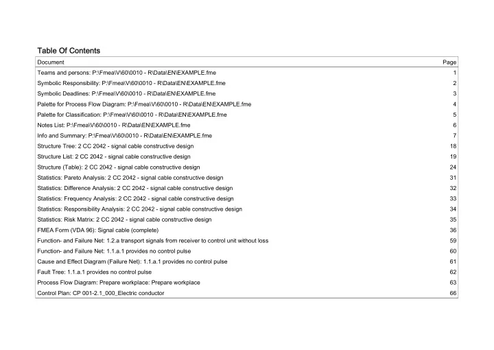
Document Page Teams and persons: P:\Fmea\V\60\0010 - R\Data\EN\EXAMPLE.fme 1 Symbolic Responsibility: P:\Fmea\V\60\0010 - R\Data\EN\EXAMPLE.fme 2 Symbolic Deadlines: P:\Fmea\V\60\0010 - R\Data\EN\EXAMPLE.fme 3 Palette for Process Flow Diagram: P:\Fmea\V\60\0010 - R\Data\EN\EXAMPLE.fme 4 Palette for Classification: P:\Fmea\V\60\0010 - R\Data\EN\EXAMPLE.fme 5 Notes List: P:\Fmea\V\60\0010 - R\Data\EN\EXAMPLE.fme 6 Info and Summary: P:\Fmea\V\60\0010 - R\Data\EN\EXAMPLE.fme 7 Structure Tree: 2 CC 2042 - signal cable constructive design 18 Structure List: 2 CC 2042 - signal cable constructive design 19 Structure (Table): 2 CC 2042 - signal cable constructive design 24 Statistics: Pareto Analysis: 2 CC 2042 - signal cable constructive design 31 Statistics: Difference Analysis: 2 CC 2042 - signal cable constructive design 32 Statistics: Frequency Analysis: 2 CC 2042 - signal cable constructive design 33 Statistics: Responsibility Analysis: 2 CC 2042 - signal cable constructive design 34 Statistics: Risk Matrix: 2 CC 2042 - signal cable constructive design 35 FMEA Form (VDA 96): Signal cable (complete) 36 Function- and Failure Net: 1.2.a transport signals from receiver to control unit without loss 59 Function- and Failure Net: 1.1.a.1 provides no control pulse 60 Cause and Effect Diagram (Failure Net): 1.1.a.1 provides no control pulse 61 Fault Tree: 1.1.a.1 provides no control pulse 62 Process Flow Diagram: Prepare workplace: Prepare workplace 63 Control Plan: CP 001-2.1_000_Electric conductor 66