
SLIDE 1
Medium Access Protocols Summary of MAC protocols
- What do you do with a shared media?
– Channel Partitioning, by time, frequency or code
- Time Division,Code Division, Frequency Division
– Random partitioning (dynamic),
- ALOHA, S-ALOHA, CSMA, CSMA/CD
- carrier sensing: easy in some technologies (wire), hard in others
(wireless)
- CSMA/CD used in Ethernet
– Taking Turns
- polling from a central cite, token passing
LAN technologies
Data link layer so far:
– services, error detection/correction, multiple access
Next: LAN technologies
– addressing – Ethernet – hubs, bridges, switches – 802.11 – PPP – ATM
LAN Addresses and ARP
32-bit IP address:
- network-layer address
- used to get datagram to destination network
LAN (or MAC or physical) address:
- used to get datagram from one interface to another
physically-connected interface (same network)
- 48 bit MAC address (for most LANs)
burned in the adapter ROM
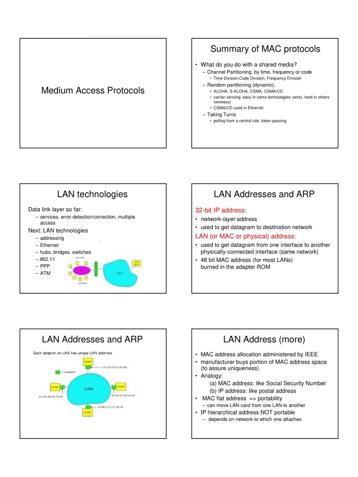
LAN Addresses and ARP
Each adapt er on LAN has unique LAN addr ess
LAN Address (more)
- MAC address allocation administered by IEEE
- manufacturer buys portion of MAC address space
(to assure uniqueness)
- Analogy:
(a) MAC address: like Social Security Number (b) IP address: like postal address
- MAC flat address => portability
– can move LAN card from one LAN to another
- IP hierarchical address NOT portable