cis 81 protocol scenarios for layers 2 and 3
play

CIS 81 Protocol Scenarios for Layers 2 and 3 Beta Date: 9/1/05 - PDF document

CIS 81 Protocol Scenarios for Layers 2 and 3 Beta Date: 9/1/05 Written by Rick Graziani Cabrillo College graziani@cabrillo.edu I have tried to catch as many of the typos and other issues (the joy of copy and paste within the document,


  1. CIS 81 Protocol Scenarios for Layers 2 and 3 Beta Date: 9/1/05 Written by Rick Graziani Cabrillo College graziani@cabrillo.edu I have tried to catch as many of the typos and other issues (the joy of ‘copy and paste’ within the document, but if you find any errors, please let me know at graziani@cabrillo.edu). Topology
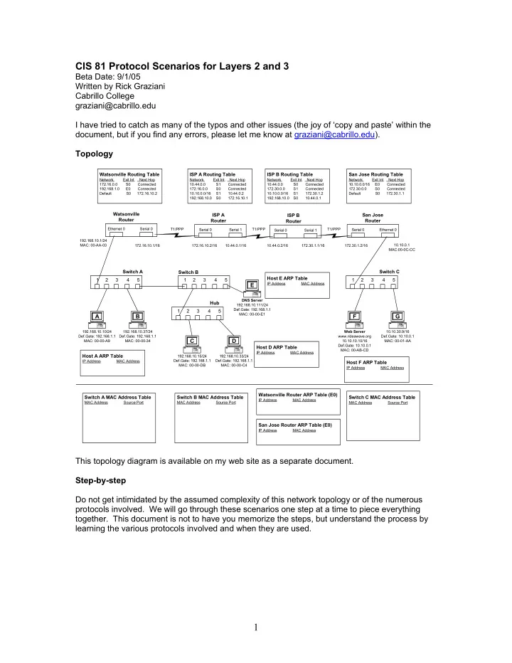
 Watsonville Routing Table ISP A Routing Table ISP B Routing Table San Jose Routing Table Network Exit Int. Next Hop Network Exit Int. Next Hop Network Exit Int. Next Hop Network Exit Int. Next Hop 172.16.0.0 S0 Connected 10.44.0.0 S1 Connected 10.44.0.0 S0 Connected 10.10.0.0/16 E0 Connected 192.168.1.0 E0 Connected 172.16.0.0 S0 Connected 172.30.0.0 S1 Connected 172.30.0.0 S0 Connected Default S0 172.16.10.2 10.10.0.0/16 S1 10.44.0.2 10.10.0.0/16 S1 172.30.1.2 Default S0 172.30.1.1 192.168.10.0 S0 172.16.10.1 192.168.10.0 S0 10.44.0.1 Watsonville ISP A San Jose ISP B Router Router Router Router Ethernet 0 Serial 0 T1/PPP Serial 0 Serial 1 T1/PPP T1/PPP Serial 0 Ethernet 0 Serial 0 Serial 1 192.168.10.1/24 MAC: 00-AA-03 172.16.10.1/16 172.16.10.2/16 10.44.0.1/16 10.44.0.2/16 172.30.1.1/16 172.30.1.2/16 10.10.0.1 MAC:00-0C-CC Switch A Switch C Switch B Host E ARP Table 1 2 3 4 5 1 2 3 4 5 1 2 3 4 5 E IP Address MAC Address DNS Server Hub 192.168.10.111/24 Def.Gate: 192.168.1.1 1 2 3 4 5 MAC: 00-00-E1 A B F G 192.168.10.10/24 192.168.10.37/24 Web Server 10.10.30.9/16 Def.Gate: 192.168.1.1 Def.Gate: 192.168.1.1 www.rideawave.org Def.Gate: 10.10.0.1 C D MAC: 00-00-A9 MAC: 00-00-34 10.10.10.10/16 MAC: 00-01-AA Def.Gate: 10.10.0.1 Host D ARP Table MAC: 00-AB-CD IP Address MAC Address Host A ARP Table 192.168.10.15/24 192.168.10.33/24 IP Address MAC Address Def.Gate: 192.168.1.1 Def.Gate: 192.168.1.1 Host F ARP Table MAC: 00-00-DB MAC: 00-00-C4 IP Address MAC Address Watsonville Router ARP Table (E0) Switch A MAC Address Table Switch B MAC Address Table Switch C MAC Address Table IP Address MAC Address MAC Address Source Port MAC Address Source Port MAC Address Source Port San Jose Router ARP Table (E0) IP Address MAC Address This topology diagram is available on my web site as a separate document. Step-by-step Do not get intimidated by the assumed complexity of this network topology or of the numerous protocols involved. We will go through these scenarios one step at a time to piece everything together. This document is not to have you memorize the steps, but understand the process by learning the various protocols involved and when they are used. 1

  2. Scenario A: Intra-network communications – Host A pinging Host D Assumptions o Hosts: All ARP tables are empty o Switches: All MAC Address tables are empty Host A issues the command: C:\> ping 192.168.10.33 (Windows) or # ping 192.168.10.33 (Linux/Unix) Step 1: ICMP Echo Request Ethernet Header IP Header ICMP Message Ether. (Layer 2) (Layer 3) (Layer 3) Tr. Ethernet Ethernet Frame Source IP Add. Type Code Check- ID Seq. Data FCS Destination Source Type Dest. IP Add. 0 or 8 0 sum Num. Address Address Protocol field (MAC) (MAC) ICMP message is encapsulated in an IP packet. Host A (TCP/IP stack) completes the information for ICMP Echo Request and IP including: o ICMP o Type: 8 o Code: 0 o IP o Source IP Address: 192.168.10.10 o Destination IP Address: 192.168.10.33 o Protocol Field: 1 (ICMP) Step 2: Ethernet Encapsulation Et hernet Header IP Header ICMP Message Ether. (Layer 2) (Layer 3) (Layer 3) Tr. Et hernet Ethernet Frame Source IP Add. Type Code Check- ID Seq. Data FCS D estination Source Type Dest. IP Add. 0 or 8 0 sum Num. Addr ess Address Protocol field (M AC) (MAC) IP Packet is now ready to be encapsulated in an Ethernet frame. Host A knows the Source MAC address for the Ethernet frame, it’s own NIC MAC address, but needs a Destination MAC Address. This IP packet is temporarily buffered in Host A’s memory. 2

  3. Destination Host or Default Gateway What is the Destination MAC address? o The Destination MAC address is either the Destination MAC Address of the host with the Destination IP Address in the packet or that of the Default Gateway. This is depending upon whether the Destination IP Address in the IP packet is on the same network as this host. o The sending host needs to determine whether the packet’s Destination IP Address is on the same network as itself (the Source IP Address in the IP Packet) or on a different network. o The sending host knows its own network address, by doing an “AND” operation on its IP Address and the Network (Subnet) Mask. o Using the same subnet mask (if the hosts were on the same network, they would have the same mask), the sending host performs an AND operation on the Destination IP Address. o If the results from the two AND operations are the same (both hosts have the same network address). The sending host then knows that the destination host is on its same network. o The Ethernet Destination Address in the frame will be that of the destination host, the host with the Destination IP Address in the IP packet. o If the results from the two AND operations are NOT the same (both hosts have different network addresses), then the sending host knows that the destination host is on a different network. o The Ethernet Destination Address in the frame will be that of the default gateway (router). At this point the IP Address of the “next hop”, is either the final destination host itself or the default gateway. Now, we need to find the MAC Destination Address of that IP Address. Ethernet Header IP Header ICMP Message Ether. (Layer 2) (Layer 3) (Layer 3) Tr. Ethernet Ethernet Frame Source IP Add. Type Code Check- ID Seq. Data FCS Destination Source Type Dest. IP Add. 0 or 8 0 sum Num. Address Address Protocol field (MAC) (MAC) If the source and destination IP addresses in the IP packet are on the same network, then the Ethernet Destination MAC Address will be the MAC Address of the same device as the destination IP address. If the source and destination IP addresses in the IP packet are on different networks, then the Ethernet Destination MAC Address wiil be the MAC Address of the default gateway (router). Router Ethernet 0 Serial 0 3

  4. In this example, the destination host is on the same network , 192.168.10.0. So, the Ethernet Destination MAC Address will be that of the destination host, the Destination IP Address in the packet. Et hernet Header IP Header ICMP Message Ether. (Layer 2) (Layer 3) (Layer 3) Tr. Et hernet Ethernet Frame Source IP Add. Type Code Check- ID Seq. Data FCS D estination Source Type Dest. IP Add. 0 or 8 0 sum Num. Addr ess Address Protocol field (M AC) (MAC) Switch A Switch B 1 2 3 4 5 1 2 3 4 5 E DNS Server Hub 192.168.10.111/24 Def.Gate: 192.168.1.1 1 2 3 4 5 MAC: 00-00-E1 A B 192.168.10.10/24 192.168.10.37/24 Def.Gate: 192.168.1.1 Def.Gate: 192.168.1.1 C D MAC: 00-00-A9 MAC: 00-00-34 Host A ARP Table 192.168.10.15/24 192.168.10.33/24 Def.Gate: 192.168.1.1 Def.Gate: 192.168.1.1 IP Address MAC Address MAC: 00-00-DB MAC: 00-00-C4 Step 3: ARP (Address Resolution Protocol) Host A knows the Destination IP Address of Host D (192.168.10.33), but needs to know the MAC Address of Host D. Host A will now look in it’s ARP table. Host A ARP Table IP Address MAC Address The ARP Table does not contain this information. To view the ARP table use the command: arp -a (Windows and Linux/Unix) 4

  5. ARP Request Host A issues an ARP Request, asking the device with the IP Address of 192.168.10.33 to reply with its MAC address. So, before the ping (ICMP Echo Request) can even be sent out, Host A must first send out an ARP Request. (This is why the first ping will sometimes take longer or even timeout.) The ICMP Echo Request is buffered by Host A. E thernet Header Ethernet Data – 28 byte ARP request/reply Et hernet Ethernet Frame ARP Sender’s Sender’s Target’s Target’s D estination Source Type headers Ethernet Address IP Address Ethernet Address IP Address Addr ess Address , i.e. op (MAC) (MAC) (M AC) (MAC) field Host A (TCP/IP stack and OS) completes the information for ARP and Ethernet including: o ARP o op field : ARP request = 1 o Sender’s MAC Address: 00-00-A9 o Sender’s IP Address: 192.168.10.10 o Target’s MAC Address: Blank o Target’s IP Address: 192.168.10.33 o Ethernet header o Destination MAC Address: Broadcast (FF-FF-FF-FF-FF-FF) o Source MAC Address: 00-00-A9 o Type: 0x806 (ARP) The ARP Request is sent out as a Layer 2 broadcast, to all devices on the network. Step 4: Transmission of the ARP Request, Switches and Hubs Host A now transmits the ARP Request. Switch A Switch B 1 2 3 4 5 1 2 3 4 5 E DNS Server Hub 192.168.10.111/24 Def.Gate: 192.168.1.1 1 2 3 4 5 MAC: 00-00-E1 A B 192.168.10.10/24 192.168.10.37/24 Def.Gate: 192.168.1.1 Def.Gate: 192.168.1.1 C D MAC: 00-00-A9 MAC: 00-00-34 Host A ARP Table 192.168.10.15/24 192.168.10.33/24 Def.Gate: 192.168.1.1 Def.Gate: 192.168.1.1 IP Address MAC Address MAC: 00-00-DB MAC: 00-00-C4 5

Download Presentation
Download Policy: The content available on the website is offered to you 'AS IS' for your personal information and use only. It cannot be commercialized, licensed, or distributed on other websites without prior consent from the author. To download a presentation, simply click this link. If you encounter any difficulties during the download process, it's possible that the publisher has removed the file from their server.

Recommend


More recommend