Structural Integrity Evaluation of High-Temperature Wedge Flowmeter - - PDF document

structural integrity evaluation of high temperature wedge
SMART_READER_LITE
LIVE PREVIEW

Structural Integrity Evaluation of High-Temperature Wedge Flowmeter - - PDF document

Transactions of the Korean Nuclear Society Virtual Spring Meeting July 9-10, 2020 Structural Integrity Evaluation of High-Temperature Wedge Flowmeter According to an Elevated Temperature Design Rule Jae-Hun Cho a , Hyeong-Yeon Lee a * , Jewhan


slide-1
SLIDE 1

Transactions of the Korean Nuclear Society Virtual Spring Meeting July 9-10, 2020

Structural Integrity Evaluation of High-Temperature Wedge Flowmeter According to an Elevated Temperature Design Rule

Jae-Hun Cho a, Hyeong-Yeon Lee a*, Jewhan Lee a

a Korea Atomic Energy Research Institute,989-111, Daedeok-Daero, Yuseong-gu, Daejeon, Korea *Corresponding author: hylee@kaeri.re.kr

  • 1. Introduction

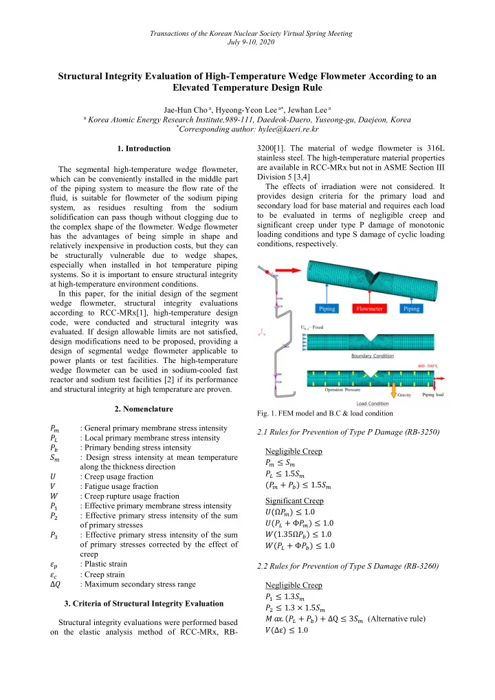
The segmental high-temperature wedge flowmeter, which can be conveniently installed in the middle part

  • f the piping system to measure the flow rate of the

fluid, is suitable for flowmeter of the sodium piping system, as residues resulting from the sodium solidification can pass though without clogging due to the complex shape of the flowmeter. Wedge flowmeter has the advantages of being simple in shape and relatively inexpensive in production costs, but they can be structurally vulnerable due to wedge shapes, especially when installed in hot temperature piping

  • systems. So it is important to ensure structural integrity

at high-temperature environment conditions. In this paper, for the initial design of the segment wedge flowmeter, structural integrity evaluations according to RCC-MRx[1], high-temperature design code, were conducted and structural integrity was

  • evaluated. If design allowable limits are not satisfied,

design modifications need to be proposed, providing a design of segmental wedge flowmeter applicable to power plants or test facilities. The high-temperature wedge flowmeter can be used in sodium-cooled fast reactor and sodium test facilities [2] if its performance and structural integrity at high temperature are proven.

  • 2. Nomenclature

: General primary membrane stress intensity 

: Local primary membrane stress intensity 

: Primary bending stress intensity  : Design stress intensity at mean temperature along the thickness direction  : Creep usage fraction  : Fatigue usage fraction  : Creep rupture usage fraction 

: Effective primary membrane stress intensity 

: Effective primary stress intensity of the sum

  • f primary stresses

: Effective primary stress intensity of the sum

  • f primary stresses corrected by the effect of

creep  : Plastic strain  : Creep strain Δ : Maximum secondary stress range

  • 3. Criteria of Structural Integrity Evaluation

Structural integrity evaluations were performed based

  • n the elastic analysis method of RCC-MRx, RB-

3200[1]. The material of wedge flowmeter is 316L stainless steel. The high-temperature material properties are available in RCC-MRx but not in ASME Section III Division 5 [3,4] The effects of irradiation were not considered. It provides design criteria for the primary load and secondary load for base material and requires each load to be evaluated in terms of negligible creep and significant creep under type P damage of monotonic loading conditions and type S damage of cyclic loading conditions, respectively.

  • Fig. 1. FEM model and B.C & load condition

2.1 Rules for Prevention of Type P Damage (RB-3250) Negligible Creep 

 ≤ 

 ≤ 1.5

(

 +  ) ≤ 1.5

Significant Creep (Ω

) ≤ 1.0

(

 + Φ ) ≤ 1.0

(1.35Ω

) ≤ 1.0

(

 + Φ ) ≤ 1.0

2.2 Rules for Prevention of Type S Damage (RB-3260) Negligible Creep 

 ≤ 1.3

 ≤ 1.3 × 1.5

 . (

 +  ) + ∆Q ≤ 3 (Alternative rule)

(∆ε) ≤ 1.0

slide-2
SLIDE 2

Transactions of the Korean Nuclear Society Virtual Spring Meeting July 9-10, 2020

Significant Creep 1.25

 +  < 1%

1.25

 +  < 3%

Creep-fatigue damage [(∆), ()] < [0.3,0.3]

  • 4. Finite Element Model & Load Condition

4.1 Finite Element Model The commercial software of ANSYS APDL ver.17.2[5] was used for the present finite element

  • analyses. A 3D finite element modeling was conducted

for the parts of wedge flowmeter and connecting pipes as shown in Fig. 1 with the following 3D element types

  • f ANSYS.

Element type I. SOLID185 (8-node Structural Solid) II. SOLID70 (8-node Thermal Solid) Total number of elements and nodes are 25,117 and 33,614, respectively. 3.2 Boundary and Load Conditions The boundary conditions and load conditions in the 3D FE model is shown in Fig. 1. In the case of mechanical boundary conditions, the left end of the flowmeter is restricted only to the axial and circumference directions, while the right end is not given a separate constraint to apply a blow-off load by piping load and operation pressure. As for thermal boundary conditions, conservative assumptions were made to give full insulation conditions outside the flowmeter and heat transfer conditions (film coefficient:10,000 W/) inside the flowmeter. Load conditions are classified according to the type

  • f load and assigned as below. The operation conditions

are assumed to be 50 cycles per year during the design life of 20 years and the hold time at hot temperature during one cycle is assumed to be 150 hours. Structural loads 1) Sustained load I. Dead weight (pipe, sodium and insulation) II. Design & level A operation pressure. (0.5 MPa) 2) Occasional load I. Earthquake load Thermal Loads 1) Level A operation temperature (400 ℃, 500 ℃)

  • 5. FE Analysis of Wedge Flowmeter

5.1 Finite Element Analysis and Integrity Evaluation

  • Fig. 2 shows distributions of the stress intensity

under structural loads and thermal loads. As shown in

  • Fig. 2, quite high stress intensity of maximum 306 MPa
  • ccurred under the structural load at the geometrically

discontinuous region of the wedge. In the meantime, maximum stress intensity of 291 MPa under the thermal load in operation temperature (400℃) occurred at the geometrically discontinuous region of the wedge. Stress linearizations were conducted over the two sections as shown in Fig. 3. All design evaluations were conducted with high- temperature design evaluation program

  • f

HITEP_RCC-MRx [6] developed by KAERI based on most recent version of RCC-MRx. The integrity evaluations according to RCC-MRx with HITEP_RCC-MRx showed that limits were exceeded at the section of A as shown below. Negligible Creep of type P damage (unit: MPa) 

 = 175.2 ≤ (= 87.0)

: Not OK 

 = 175.2 ≤ 1.5(= 130.5)

: Not OK (

 +  ) = 266.8 ≤ 1.5( =130.5)

: Not OK Negligible Creep of type S damage (unit: MPa) 

 = 214.9 ≤ 1.3(= 113.1)

: Not OK 

 = 292.7 ≤ 1.3 × 1.5(= 169.7)

: Not OK (∆ε) = 1.36 ≤ 1.0 : Not OK

  • Fig. 2. Distribution of stress intensity under structural loads

(upper) and thermal loads (400℃) (lower)

slide-3
SLIDE 3

Transactions of the Korean Nuclear Society Virtual Spring Meeting July 9-10, 2020

  • Fig. 3. Positions of section line for stress linearization
  • Fig. 4. Design Modification of Segmental Wedge Flowmeter

5.2 Design Modification Because design limits on load-controlled stress limits were not satisfied, a reinforcement plate was attached to strengthen the wedge structure as shown in Fig. 4. The reinforcement plate was designed so as to reduce the stress level and satisfy the structural integrity. 5.3 Integrity evaluation of modified wedge model

  • Fig. 5 shows the stress intensity distributions under

structural and thermal loads. The maximum stress intensity under the structural load was 59.6 MPa at the geometrically discontinuous region of the wedge, which is the value reduced a lot from 306 MPa in case of no reinforcement plate. In addition, the maximum stress intensity under the thermal load at

  • perating

temperature of 500 ℃ was 98.4 MPa at the geometrically discontinuous region of the wedge. The evaluation section was the same as before. When stress components before and after shape modification for the A section where the greatest stress

  • ccurred were compared, it was confirmed that the axial

membrane stress was reduced by 30% and the bending stress was reduced by 34%. Table I~IV show the evaluation results at the section

  • f A and B under level A condition. It was shown that

evaluation results under the level A condition for the modified design were well within the allowable limits.

  • Fig. 5. Distributions of stress intensities under structural load

(upper) and thermal load (500℃) (lower) Table I: Evaluation results of type P damages (negligible creep)

Section Criteria Max. Stress (MPa) Allowable stress (MPa) Ratio A 

54.2 87.0a 80.0b 0.6 0.7  54.2 130.5 a 120.0 b 0.4 0.5 + 85.8 130.5 a 120.0 b 0.7 0.7 B 

18.8 87.0 a 80.0 b 0.2 0.2  18.8 130.5 a 120.0 b 0.1 0.2 + 30.6 130.5 a 120.0 b 0.2 0.3

a: allowable stress at operation temperature 400℃ b: allowable stress at operation temperature 500℃

Table II: Evaluation results of type S damages (negligible creep)

Section Criteria Max. Stress (MPa) Allowable stress (MPa) Ratio A 

54.9 113.1 a 104.0 b 0.5 0.5  85.8 169.7 a 156.0 b 0.5 0.6 (∆ε) 1E-6 1.0

  • B

31.7 113.1 a 104.0 b 0.3 0.3  42.1 169.7 a 156.0 b 0.3 0.3

slide-4
SLIDE 4

Transactions of the Korean Nuclear Society Virtual Spring Meeting July 9-10, 2020

(∆ε) 1.0

  • a: allowable stress at operation temperature 400℃

b: allowable stress at operation temperature 500℃

Table III: Evaluation results of type P damages (significant creep)

Section Criteria Max. Stress (MPa) Allowable stress (MPa) Ratio A (Ω

)

0.0007 1.0 0.0 ( + Φ

)

0.2127 1.0 0.2 (1.35Ω

)

0.0070 1.0 0.0 ( + Φ) 0.0989 1.0 0.1 B (Ω

)

0.0000 1.0 0.0 ( + Φ

)

0.0000 1.0 0.0 (1.35Ω

)

1E-5 1.0 0.0 ( + Φ) 0.0001 1.0 0.0

Table IV: Evaluation results of type S damages (significant creep)

Section Criteria Max. Stress (MPa) Allowable stress (MPa) Ratio A 1.25

( + )

0.0333 113.1 a 104.0 b 0.5 0.5 1.25

( + )

0.1851 169.7 a 156.0 b 0.5 0.6 (∆ε) 0.3

  • Fig. 6

() 0.0001 0.3 B 1.25

( + )

0.0083 113.1 a 104.0 b 0.3 0.3 1.25

( + )

0.0150 169.7 a 156.0 b 0.3 0.3 (∆ε) 0.3

  • Fig. 6

() 0.3

a: allowable stress at operation temperature 400℃ b: allowable stress at operation temperature 500℃

The evaluation results of creep-fatigue damage were also confirmed to be within the allowable limits (bilinear solid line), as shown in Fig. 6, in which both fatigue damage ( ) and creep damage (  ) were negligible for the section of A and B.

  • Fig. 6. Creep-fatigue damage envelope at section A(L) and

section B(R) of for the modified FE model

  • 6. Conclusions

In this paper, structural integrity evaluations for the high-temperature segmental wedge flowmeter were performed according to French high-temperature design rule of RCC-MRx. The initial design of wedge flowmeter did not satisfy design allowable limits of the RCC-MRx for level A operation conditions, and a design modification was conducted to reduce the stress level under level A operating conditions. The load- controlled stress limits, inelastic strain limits and creep- fatigue limits of the design rules were all satisfied for the modified wedge flowmeter with reinforcement plate. As future study, further optimization of wedge flowmeter design will be conducted with consideration

  • f various load conditions.

ACKNOWLEDGEMENT This work was supported by the National Research Foundation of Korea (NRF) grant funded by the Korea government (MSIP). (No. 2012M2A8A2025635) REFERENCES

[1] RCC-MRx Code, Section III, Tome 1, Subsection B, Class 1 N1Rx Reactor Components its Auxiliary Systems and Supports, AFCEN, Lyon, France, 2018. [2] H.-Y. Lee, J.-H. Eoh and J.-Y. Jeong, Elevated temperature design and integrity evaluation of a large-scale sodium test facility, STELLA-2, Nuclear Engineering and Design, 346, pp.54-66, 2019. [3] ASME, BPVC Section III, Division 5, High Temperature Reactors, ASME, New York, 2017. [4] H.-Y. Lee, Comparison of elevated temperature design codes of ASME Subsection NH and RCC-MRx, Nuclear Engineering and Design, 308, pp.142-153, 2016. [5] ANSYS User’s manual, version 17.2. [6] H.-Y. Lee, M.-G. Won and N.-S. Huh, HITEP_RCC-MRX program for the support of elevated temperature design evaluation and defect assessment, Journal of pressure vessel technology, Transactions of ASME, 141, October, 051205- 1~13, 2019.