strength of self piercing riveted joints for cfrp
play

STRENGTH OF SELF-PIERCING RIVETED JOINTS FOR CFRP/ALUMINIUM SHEETS - PDF document

18 TH INTERNATIONAL CONFERENCE ON COMPOSITE MATERIALS STRENGTH OF SELF-PIERCING RIVETED JOINTS FOR CFRP/ALUMINIUM SHEETS L. Kroll 1 , S. Mueller 1,3 *, R. Mauermann 2 , R. Gruetzner 2 1 Chemnitz University of Technology, Institute of Lightweight


  1. 18 TH INTERNATIONAL CONFERENCE ON COMPOSITE MATERIALS STRENGTH OF SELF-PIERCING RIVETED JOINTS FOR CFRP/ALUMINIUM SHEETS L. Kroll 1 , S. Mueller 1,3 *, R. Mauermann 2 , R. Gruetzner 2 1 Chemnitz University of Technology, Institute of Lightweight Structures, Chemnitz, Germany, 2 Fraunhofer Institute for Machine Tools and Forming Technology, Dresden, Germany 3 Lightweight Structures Engineering GmbH, Chemnitz, Germany * Corresponding author (sascha.mueller@mb.tu-chemnitz.de) Keywords : joining, self-piercing rivet, CFRP, aluminium sheets 1 Introduction GmbH. When the yield strength of the self-piercing rivet material was too low, the self-piercing rivet Multi material design in lightweight applications is was deformed before it could pierce the top CFRP most probable the challenging task in the future. laminate. If the yield strength of the self-piercing Only the right material in the right place can exploit 
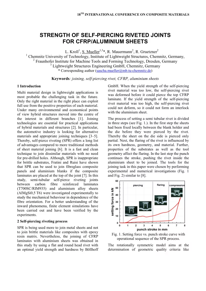
rivet material was too high, the self-piercing rivet full use from the positive properties of each material. could not deform, so it could not form an interlock Under many environmental and economical points with the aluminium sheet. of view hybrid structures moved into the centre of the interest in different branches [1]. Joining The process of setting a semi tubular rivet is divided technologies are essential for practical applications in three steps (see Fig. 1.). In the first step the sheets of hybrid materials and structures [2]. In particular, had been fixed locally between the blank holder and the automotive industry is looking for alternative the die before they were pierced by the rivet. materials and appropriate joining techniques [3–5]. Thereby the sheet on the die side is pierced only Thereby, self-pierce riveting (SPR) offers a long list partial. Next, the flaring of the rivet is influenced by its own hardness, geometry, and material. Further, of advantages compared to more traditional methods of sheet material joining [6]. It is a fast and clean properties of the substrates as well as the tool technique to join dissimilar materials with no need geometry affect the flaring. In the last step the punch for pre-drilled holes. Although, SPR is inappropriate continues the stroke, pushing the rivet inside the for brittle substrates, Fratini and Ruisi have shown aluminium sheet to be joined. The tools for the that SPR can be used to join fibreglass composite joining task in this paper were chosen by performing panels and aluminium blanks if the composite experimental and numerical investigations (Fig. 1 laminates are placed at the top of the joint [7]. In this and Fig. 2) similar to [8]. study, semi-tubular self-pierce riveting joints between carbon fibre reinforced laminates (T700SC/RIM935) and aluminium alloy sheets (AlMgSi0,5 T6) were investigated experimentally to study the mechanical behaviour in dependence of the fibre orientation. For a better understanding of the inward phenomena, finite element simulations have been carried out and have been verified by the experiments. 2 Self-piercing riveting process SPR is being used more to join metal sheets and not to join brittle materials like composites with epoxy Fig. 1. Setting force vs. punch stroke curve with resin matrix. Nevertheless, the joining of CFRP operational sequence of the SPR process. laminates with aluminium sheets was obtained in this study by using a flat and round head rivet with The rotationally symmetric model aims at the an optimal yield strength and hardness by Böllhoff determination of geometric quality criteria like

  2. undercut, deformation of the rivet and forming force. The upper part of the core is excessively damaged. It considers plastic material behaviour for the Fibre fracture as well as inter fibre fracture can be aluminium sheet and the tubular rivet while the fibre found in this region while the structure of the reinforced material is modelled purely elastic. To laminate is almost unrecognisable. The lower part of reduce the effort of the numerical model the element the core still reveals the laminate layup, but the stiffness of elements exceeding the yield point is former flat and plane layers are curved after the reduced. In spite of the chosen assumptions the riveting process. comparison of simulative and experimental results (Fig. 2) is in accordance with geometric quality criteria. While the deformation of the rivet matches with the measurements in the micro section the simulation underestimates the deformation of the aluminium sheet in the area of the die. Fig. 3. Micro section of a semi tubular self-piercing rivet between a carbon fibre reinforced laminate Fig. 2. Comparison between experimental and ([0/90] 4S -layup) and an aluminium alloy sheet. simulated section; right: micro section; left: max principal stress distribution at the end of the joining procedure (2D-model). detail A 3 Micro section analyses The micro-sectional view of a manufactured joint is detail B shown in Fig. 3. Hereby a cross-ply-laminate with A [0/90] 4S -layup and an extruded aluminium alloy sheet, both 2 mm in thickness, were joined point wise by SPR. The rivet was pushed through the top CFRP laminate into the bottom sheet. Then the aluminium sheet flew into the die and the rivet shank was flared in radial direction to form a mechanical detail C interlock. This joint has no through-hole and B C therefore is impermeable to air and fluids; it is ‘water tight’. In contrast formed bulges may not be Fig. 4. Close-up of the deformed and damaged acceptable regarding aesthetic aspects [6]. laminate structure inside the rivet shank. A close-up of the laminate structure is shown in In Fig. 5, the laminate structure outside of the rivet Fig. 4. It can be observed that the punched core of is depicted more precisely. All layers are curved in the CFRP-laminate is strongly deformed and the direction of rivet setting. The curvature radius of the bottom layer is taller than the curvature radius of damaged. Due to the fact that the punched core the top layer. Both, top and bottom layer, seem to be remains in the semi-hollow shank, this joining mostly undamaged while fibre fracture and technique produces no waste material and makes the delamination occur near the middle layers. The riveting process clean. layers in 0°-orientation (brighter layers with fibres

  3. PAPER TITLE running from left to right) were cut by the rivet. In the middle region, they are also broken in a characteristic distance to the rivet shank. Because of their fixed length, they leave the 0°-orientation. The layers in 90°-orientation (perpendicular to the micro section) are deformed without fibre fracture. These Fig. 6. Dimensions of the specimen. layers show a sort of shearing bands between the To determine strength and fracture mechanisms in fibres. Although the matrix – made of epoxy resin – depending on different orientation angles φ , the tests has a brittle behaviour, it shows no inter fibre were performed under φ = 0°, φ = 15°, φ = 30° and fracture. Furthermore, it is assumed that the matrix φ = 45° with cross-ply-laminates with a [0/90] 4S - becomes plastically deformable due to the high layup. All other geometric, material and process compression stress during the riveting process. This parameters are constant in these tests. effect had already been observed [9]. detail C Al CFRP σ N ϕ A C Fig. 7. Quasi-static test specimen with the cross-ply- detail A laminate under φ = 0°, φ = 15°, φ = 30° and φ = 45° detail B to the loading direction. Load vs. displacement curves for quasi-static single lap shear tests (φ = 0°) are shown for five specimens in Fig. 8. The marked points A, B...E refer to the B images in Fig. 9. Fig. 5. Close-up of the deformed and damaged 5 D laminate structure near the rivet shank under the 4 C rivet head. load in kN 3 4 Mechanical behaviour of SPR joints E Many research studies are focused on comparisons 2 B of the mechanical behaviour of joints manufactured 1 by various techniques; like spot welding, press A joining, pop riveting, self-tapping screws, self-pierce 0 riveting and more. A summary for metal materials is 0 1 2 3 4 given by He et al. in [8]. In this study, the behaviour stroke in mm of SPR joints was investigated with focus on the Fig. 8. Load vs. displacement curves for performed CFRP composite by using single lap shear tests. The quasi- static single lap shear tests for φ = 0°. testing speed was set for all specimens at a displacement controlled quasi-static loading with These images of a lap shear test give a good 2 mm/min. The specimens have a gauge length of impression of the complex mechanism of the joint 95 mm and a width of 45 mm. The aluminium sheets specimen under loading. Beginning from the as well as the CFRP laminates were 2 mm in unloaded state A all specimens showed a reversible thickness, and the rivet was placed at the centre of elastic behaviour up to 1.65 kN. Then the tip of the the 36-mm-long overlap (see Fig 6). The rivet aluminium sheet has formed a gap and the rivet has dimensions are ∅ 5.3 mm x 5.6 mm with a head begun to tilt (state B). At point C three of the five diameter of 7.7 mm. specimens showed a short break in their curves. 3

Download Presentation
Download Policy: The content available on the website is offered to you 'AS IS' for your personal information and use only. It cannot be commercialized, licensed, or distributed on other websites without prior consent from the author. To download a presentation, simply click this link. If you encounter any difficulties during the download process, it's possible that the publisher has removed the file from their server.

Recommend


More recommend