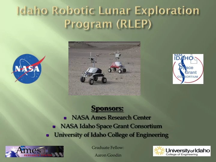
SLIDE 1 Sponsors:
- NASA Ames Research Center
- NASA Idaho Space Grant Consortium
- University of Idaho College of Engineering
Graduate Fellow: Aaron Goodin
SLIDE 2
SLIDE 3
SLIDE 4
SLIDE 5
Joined the RLEP team as a ME undergrad in
the Capstone Design Program at the University of Idaho.
Tasked with a project to create a non-
prehensile robotic manipulator to accomplish multiple tasks outlined by the Intelligent Robotics Group at NASA ARC
Initial goal was to adapt to IRG’s K10 rover
SLIDE 6 Soil Sample Collection
Dislodging K-10 Rover
Rock Chipping Soil Compaction
- Path Clearing
- Soil Relocating
Rock Flipping
- Rock Pushing
- Soil Sifting
- Tilling
- Stake Planting
SLIDE 7
Base Rotation
Shoulder Rotation
Electronic Hardware Linear Actuator
Elbow Rotation
SLIDE 8
Able to work on multi-disciplinary projects (ME, EE,
CompE, CS)
Integrating multiple designs into one final package that
has to work
Robotics = Motors
In-depth motor research Motor Control Micro processing & Programming
Applying CAD for a real purpose Spending time in the machine shop learning important
manufacturing principles
Working with a team!!! not always easy
SLIDE 9
Applied for ISGC fellowship and became the
next RLEP fellow.
Traveled to NASA ARC for the first summer
internship.
Mentored in the design and fabrication of the
second RLEP robotic platform.
SLIDE 10
Gained project management experience by co-
managing a team of Robotics Academy Students to improve L07
Mentored students to help them in the design
process
Worked to specify the next RLEP project
SLIDE 11 Old Interface New and Improved Interface Improvement Areas:
- Easier navigation between joint control
- More control options
- Incorporate real time video
- Programmed Stop command
SLIDE 12 12 volt Power Supply Servo Motor Controller BS2 Board of Education DC Motor Controller DC1HV DC Converter 16 volt Lithium Ion Batteries Mini ITX board XP-08 Power Management DC123S DC Converter 6 volt Power Supply Brushless motor Controller Motor Mind Controller Boards Basic Stamps Wireless Kill Switch Wiring done by Jennifer Allen
Old Avionics New Avionics
SLIDE 13
SLIDE 14 Base Design for 3-phase direct drive motor Cam/Follower poker design used for percussive pecking
Greatly Improved Avionics Box
Bearing Mounting Frame Fastener Motor Rotor
Mounting Frame Motor Stator Base Frame
SLIDE 15
SLIDE 16
Project management experience
Learning to delegate Learning to manage: i.e. problematic team members
Advanced machining capabilities Presentations, Publishing's, Networking, and more
Leveraging Experiences
Great research opportunities
NASA related research Lunar Science Institute RLEP related research Robots going to The Moon My Thesis work NASA + RLEP = MSME Bio-Tensegrity
SLIDE 17
- a continuous TENSION network structured by discontinuous COMPRESSION
members.
- Tension members must be pre‐stressed and will never go into compression.
- No Bending or Shear stresses!!!
SLIDE 18
KENNETH SNELSON
Architect and Inventor Coined the term
Tensegrity by joining the terms: “Tension” & “Structural Integrity”
Artist Known as the “Father of
Tensegrity”
Fuller Dome: Geodesic Dome Snelson’s Tower: Needle Tower
SLIDE 19 Tetrahedron Octahedron Dodecahedron Icosahedron
- Five shapes are said to enable the construction of
tensegrity structures
- All of these shapes are based off of the equilateral
triangle
SLIDE 20
Calculated: 36,000N Max: 9,600 N
SLIDE 21 Fascia –
tissue in the body comprised of tendons, ligaments, and cartilage
dimensional web of tissue that extends from head to toe.
Tom Flemmons –
building bio- tensegrity structures in the 1970’s
SLIDE 22
LIFT ARCHITECTS
FLUIDIC ACTUATORS
VIDEO Airics Arm
SLIDE 23
DEPLOYABLE TENSEGRITIES
STRESS ANALYSIS FOR SIMPLE TENSEGRITY STRUCTURES.
Tensegrity Structures
excel at taking unknown force vectors and distributing the stress efficiently
Could be used to
package instruments being deployed that will take loads from any direction of unknown magnitude.
Use rods with given
area, length, and material properties
Apply loads with a
known direction and magnitude
Using strain gauges to
measure stress at multiple points on rods
SLIDE 24