SLIDE 1
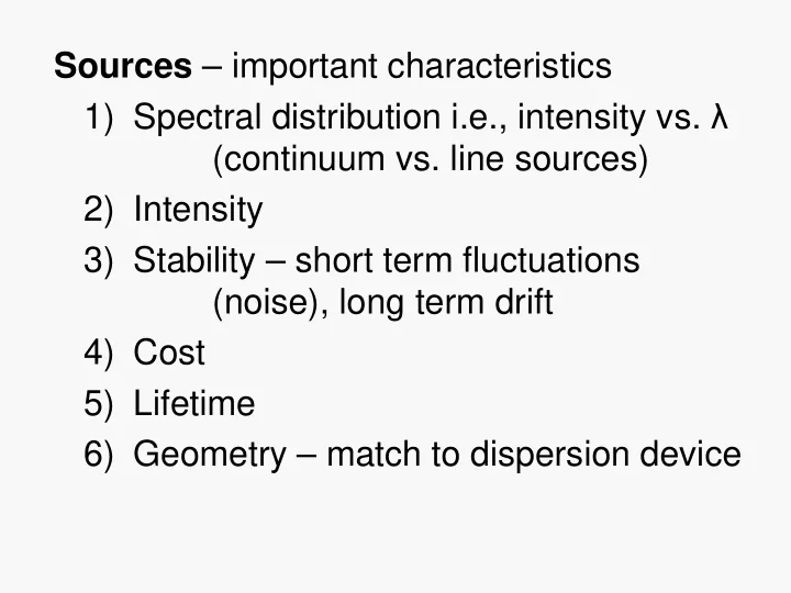
Sources – important characteristics 1) Spectral distribution i.e., intensity vs. λ (continuum vs. line sources) 2) Intensity 3) Stability – short term fluctuations (noise), long term drift 4) Cost 5) Lifetime 6) Geometry – match to dispersion device
SLIDE 2 I) CONTINUUM SOURCES
1) Thermal radiation (incandescence) – heated solid emits radiation close to the theoretical “Black Body” radiation i.e., perfect emitter, perfect absorber Behavior of Black Body
- Total power ~ T4 therefore need constant
temperature for stability when using incandescent sources
- Spectral distribution follows Planck’s radiation
law
SLIDE 3
Spectral Distribution Curves of a Tungsten (Black Body) Lamp
At higher temp -> maximum shifts to shorter wavelengths. Low temp good for IR, but visible region requires high temp. UV vis IR
SLIDE 4 IR Region thermal sources (Black Body) are: a) Nernst Glower – fused mixture of ZrO2, Y2O3, and ThO2 normally operated at 1900 oC – better for shorter IR λ’s (near IR) b) Globar – silicon carbide normally
- perated at 1200 to 1400 oC – better at
longer IR λ’s (doesn’t approach Black Body) c) Incandescent Wire – e.g., nichrome wire – cheapest way
SLIDE 5
- All operated at relatively low
temperature.
- Good for IR and give some visible
emission.
- Operated in air so will burn up if temp
goes too high Advantages
- Nernst Glower – low power consumption,
- perates in air, long lifetime
- Globar – more stable than Nernst
Glower, requires more power & must be
- cooled. Long lifetime, but resistance
changes with use
SLIDE 6
SLIDE 7 Visible Region sources are: a) Glass enclosed Tungsten (W) filament - normally
- perated at ~3000 oK with inert atmosphere to
prevent oxidation. Useful from 350 nm to 2000 nm, below 350 nm glass envelope absorbs & emission weak b) Tungsten-Halogen lamps - can be operated as high as 3500 oK. More intense (high flux). Function of halogen is to form volatile tungsten- halide which redeposits W on filament, i.e., keeps filament from burning out. Requires quartz envelope to withstand high temps (which also transmits down to shorter wavelengths). Fingerprints are a problem – also car headlights
SLIDE 8 2) Gas Discharge Lamps – two electrodes with a current between them in a gas filled
- tube. Excitation results from electrons
moving through gas. Electrons collide with gas excitation emission At high pressure “smearing” of energy levels spectrum approaches continuum The higher the pressure, the greater the probability that any given molecule or atom will be perturbed by its neighbor at the moment of emission.
SLIDE 9 a) Hydrogen Lamp
source for UV absorption measurements H2 emission is from 180 nm to 370 nm limited by jacket
Line spectrum from 100 watt Hydrogen Lamp at low pressure in Pyrex
SLIDE 10
b) Deuterium Lamp – same λ distribution as H2 but with higher intensity (3 to 5 times) - D2 is a heavier molecule & moves slower so there is less loss of energy by collisions
High pressure D2 with quartz jacket
SLIDE 11 For higher intensity c) Xenon Lamp – Xe at high pressure (10-20 atm)
to get lots of collisions for broadening leading to continuum
- short life relatively
- arc wander (stabilize)
- need jolt to start
- output = f(time)
SLIDE 12
d) High Pressure Mercury Lamp – can’t completely eliminate bands associated with particular electronic transitions even at very high pressures (e.g., 100 atm)
SLIDE 13
- For UV-vis absorption spectrophotometry
usually use H2 for UV and tungsten for visible region (switching mid scan)
- Sometimes use D2 instead of H2
- For fluorescence spectrophotometry use
xenon arc lamp in scanning instruments
- Can use He below 200 nm
- Hg at low pressure is used in fixed
wavelength (non scanning) fluorometers
- Can use mixture of Hg and Xe
SLIDE 14
I) CONTINUUM SOURCES (review)
1) Thermal radiation (incandescence)
IR Region
a) Nernst Glower b) Globar c) Incandescent Wire
Visible Region
a) Tungsten filament b) Tungsten-Halogen 2) Gas Discharge Lamps (High Pressure) a) Hydrogen Lamp b) Deuterium Lamp c) Xenon Arc Lamp d) Mercury Lamp
SLIDE 15 II) LINE SOURCES
1) Gas (Vapor) Discharge Lamps at low pressure (i.e., few torr) – minimize collisional interaction so get line spectrum
- most common are Hg and Na
- often used for λ calibration
- Hg pen lamp
- fluorescent lights are another example
- also used UV detectors for HPLC
2) Hollow Cathode Lamps (HCL) – for AA 3) Electrodeless Discharge Lamps (EDL) - AA
SLIDE 16
4) Lasers (Light Amplification by Stimulated Emission of Radiation) – start with material that will exhibit stimulated emission and populate upper states typically using another light source
SLIDE 17
Pumping source used to populate upper states can be flashlamp or another laser Often use prism to select pumping wavelength Advantages of lasers 1) Intense 2) Monochromatic – very narrow band 3) Coherent – all radiation at same phase angle 4) Directional – full intensity emitted as beam
SLIDE 18
Limitations of lasers 1) High cost in many cases 2) Wavelength range is somewhat limited 3) Many operate in pulsed mode – some are continuous wave (CW) Pulsed mode lasers are not always problematic as light sources, can use pulse frequency with gated detection
SLIDE 19
Types of Lasers: a) Solid State Lasers 1) Ruby laser – Al2O3 + Cr(III) - 694.3 nm pumped with Xe arc flashlamp – pulsed (can be continuous) 2) Nd/YAG laser – yittrium aluminum garnet + Nd - 1064 nm b) Gas Lasers 1) Neutral atom – He-Ne – 632.8 nm continuous 2) Ion lasers – Ar+ or Kr+ 514.5 nm
SLIDE 20
3) Molecular lasers – CO2 (10,000 nm = 1000 cm-1) or N2 (337.1 nm) pulsed 4) Eximer lasers – inert gas + fluorine creates eximers ArF+ (193 nm), KrF+ (248 nm), XeF+ (351) pulsed c) Dye Lasers – tunable over 20 – 50 nm many dyes available for wide range of λ’s d) Semiconductor Diode Lasers – wide range of λ’s available, continuous
SLIDE 21 5) Light Emitting Diodes (LEDs)
- Semiconductor device that very efficiently produces light
as a line source
Output of 3 LEDs With bandwidths of About 25 nm
SLIDE 22
LED Packages
SLIDE 23 Older Communications LED
Fiber optic pig tail
SLIDE 24 LED Radiation Patterns
An LED is a directional light source, with the maximum emitted power in the direction perpendicular to the emitting surface. The typical radiation pattern shows that most of the energy is emitted within 20°
maximum light. Some packages for LEDs include plastic lenses to spread the light for a greater angle of visibility.
SLIDE 25 LED Device Structure
(Edge Emitting LED) One type of LED construction is to deposit three semiconductor layers on a substrate. Between p-type and n-type semiconductor layers, an active region emits light when an electron and hole recombine. The light is produced by a solid state process called
- electroluminescence. In this particular design,
the layers of the LED emit light all the way around the layered structure, and the LED structure is placed in a tiny reflective cup so that the light from the active layer will be reflected toward the desired exit direction.
SLIDE 26
Two Basic Device Designs
SLIDE 27 Wavelength Selection
Three main approaches: 1) Block off unwanted radiation –
2) Disperse radiation & select desired band – monochromator 3) Modulate wavelengths at different frequencies - interferometer FILTERS
1) Absorption – colored glass, colored film, colored solutions – cheapest way
SLIDE 28
Assortment of Glass & Quartz Optical Filters
SLIDE 29
Combining two appropriate cut-off filters produces a bandpass filter. The example shown here comes from 3 filters producing bands at 500 & 600 nm.
SLIDE 30
Two terms associated with optical filters are: 1) Effective bandwidth measured at ½ peak height 2) Nominal wavelength These filters have nominal wavelengths of 450 & 500 nm
SLIDE 31 2) Interference filters – usually Fabrey-Perot type
Incident light beam Transmitted radiation Glass layers Dielectric material (CaF or MgF) Semi-reflective metal layers
Light bounces back & forth & gets out of phase with itself unless it meets conditions for constructive interference
SLIDE 32 Condition for constructive interference mλ 2d = ------ η If distance (d) is multiple (m) of wavelength (λ) then it won’t be interfered with Concept of Order – constructive & destructive interference causes waves with different phase angles to be eliminated except if they are multiples of each other
distance between semi-reflective layers
refractive index
SLIDE 33 2) Interference filters – usually Fabrey-Perot type
Incident light beam Transmitted radiation Glass layers Dielectric material (CaF or MgF) Semi-reflective metal layers
Light bounces back & forth & gets out of phase with itself unless it meets conditions for constructive interference
“d” spacing
d
SLIDE 34 Condition for constructive interference mλ 2d = ------ η If distance (d) is multiple (m) of wavelength (λ) then it won’t be interfered with Concept of Order – constructive & destructive interference causes waves with different phase angles to be eliminated except if they are multiples of each other
distance between semi-reflective layers
refractive index
SLIDE 35
FWHM – full width at half maximum
SLIDE 36
Transmittance vs. wavelength for typical Fabrey-Perot Interference filter showing first and second order λ’s (m = 1 & m = 2)
SLIDE 37
3) Neutral density filters – reduces intensity without any λ discrimination
SLIDE 38 II) MONOCHROMATORS
source detector location Simple Prism Monochromator Entrance slit allows source radiation to illuminate the first lens which collimates the light spreading it across the face of the
- prism. Prism disperses radiation into component wavelengths
and the second lens focuses the spectrum at the focal plane. An exit slit selects the band of radiation to reach the detector. Dispersing element can be a prism or a diffraction grating. Focusing elements can be lenses or mirrors.
Focal plane
SLIDE 39
- Optical Materials – need optically
transparent materials for lenses, prisms & sample cells
- In visible region – can use glass down to
350 nm
- In the UV region – quartz is material of
choice
- In the IR region – NaCl, KBr, etc. The
heavier the atoms of the salt, the farther into the IR region (i.e., longer λ) before significant absorption occurs Problem – sensitivity to moisture
SLIDE 40 Resolution – ability to distinguish as separate, nearly identical frequencies; measured in terms of closest frequencies ∆ν in a spectrum that are distinguishable ν λ R = -----
(both dimensionless) ∆ν ∆ λ Dispersion – spread of wavelengths in space Angular Dispersion – angular range dθ over which waveband dλ is spread dθ rad
dλ nm
SLIDE 41 Linear Dispersion – distance dx over which a waveband dλ is spread in the focal plane of a monochromator dx mm
dλ nm Linear Reciprocal Dispersion – range of λ’s spread over a unit distance in the plane of a monochromator dλ nm
dx mm Related terms spectral slit width or bandwidth or bandpass = range of λ’s included in a beam of radiation measured at half max intensity
SLIDE 42 Lenses – lens equation (for a thin lens) 1 1 1
r2
Where f = focal length η = refractive index of lens material η’ = refractive index of adjacent material r1 = radius of curvature of first surface r2 = radius of curvature of second surface 1 1 1
image
i
distance to image distance to object
SLIDE 43 Focal length is important specification of a monochromator focal length (f) f/ (f number) = ------------------------------ lens clear aperature
- f/ is measure of light gathering power
- Larger f/ means getting less light
- Light gathering power ~ 1/(f/)2
Point source at f (focal point
Parallel beams
SLIDE 44
f/ of a monochromator is important if have a weak source. For lenses in series, the smallest f/ sets the overall f/ for the system. Lens Summary: 1) rugged, easy to use, inexpensive 2) can have chromatic aberrations = focal length depends on η which varies with λ – solution is to fabricate lenses out of a composite glasses so η is constant with λ. This increases cost 3) Each lens results in some light loss due to reflection
SLIDE 45 Mirrors – high quality instruments use front- surfaced mirrors for focusing which avoids chromatic aberrations
1 1 1
+ ----- f i o
Problem spherical aberrations
image
i
Spherical Mirror
SLIDE 46 Mirror problem spherical aberrations – f gets shorter as rays go off axis (this can actually be a problem for lenses also) Several solutions: 1) Just use center of mirror (or lens) – but this reduces the light-gathering power (f/ increases) 2) Use parabolic mirror (harder to make $$) 3) Use Schmidt Corrector
so they come to a good focus
Spherical Mirror
SLIDE 47
Astigmatism – for an object off axis, the horizontal and vertical focuses differ – get two images displaced from each other Numerical Aperture (NA) = sin θ angle over which a device accepts light Slits – entrance and exit slits Slits affect energy throughput & resolution Decrease slit width gain resolution & lose energy throughput Open slits wider increase signal (throughput) but lose resolution θ
SLIDE 48
Energy throughput must be sufficient for detector to measure signal with adequate precision. In practice the image of the entrance slit in a monochromator should just fill the exit slit for optimum conditions. Otherwise the larger slit establishes (i.e, limits) the resolution and the smaller slit establishes (or limits) the energy throughput. There is a theoretical minimum for slit widths imposed by diffraction.
SLIDE 49 Light exiting a monochromator exit slit has a triangular distribution Optical Efficiency = throughput x resolution Good criterion for comparing optical systems Prism < Grating < Interferometer Monochromator Monochromator
Relative power
Range of λ’s passing when set at λo bandpass or bandwidth
SLIDE 50 Dispersion Devices 1) Prisms Light bends due to η η = f (λ) dθ dθ dη Angular Dispersion = ----- = ------ x ------ dλ dη dλ Angle changes with λ the larger the better
b A
θ
A = apical angle b = base length function of prism design (i.e. angle A) function
material
SLIDE 51
Dispersion Devices 1) Prisms dθ Increasing A ----- increases but internal dη reflection is also greater (typical A value is 60o)
b A
θ
A = apical angle b = base length
SLIDE 52 Dispersion Devices 1) Prisms
dη dη
- ---- depends on material, ----- greatest at shorter λ
dλ dλ
b A
θ
A = apical angle b = base length
η λ
SLIDE 53 mm dθ Linear Dispersion
nm dλ Depends on angular dispersion and focal length For constant bandwidth, slit widths must be varied with λ to compensate for variations in dη/ dλ Stated another way, linear dispersion changes in different regions of the spectrum
SLIDE 54
Kinds of Prisms Littrow Prism & Mounting – compact design
Focal Plane Reflecting Prism
SLIDE 55 Problem with quartz prisms is that quartz is
- ptically active (optically anisotropic). With
the Littrow prism or any reflecting prism, the light travels essentially the same path in both directions and this effect is eliminated. Cornu Prism
Right handed quartz Left handed quartz 60o 30o (-) (+)
SLIDE 56
Another view of a Cornu prism
SLIDE 57 Gratings – based on diffraction & interference Transmission Gratings & Reflection Gratings consist of a series of grooves in glass or quartz
Monochromatic Radiation Grating
d
SLIDE 58
Gratings work on the principles of diffraction & interference
SLIDE 59
Grating Equation m λ = d sin β Condition for constructive interference AC = extra distance light travels for first order = d sin β For higher orders the distance gets longer
d
SLIDE 60
Reflection grating with non-normal incidence