SlideControl 2.0 TECHNOLOGY on the tissue. assumed. For the - - PDF document

slidecontrol 2 0 technology
SMART_READER_LITE
LIVE PREVIEW

SlideControl 2.0 TECHNOLOGY on the tissue. assumed. For the - - PDF document

www.envea.global PROCESS MONITORING SYSTEMS FOR SOLIDS Product Information FEATURES: Contactless throughput measurement for air slides No installations into the process 4 ... 20 mA trend signal for the fmow rate Fast recognition of Flow / No


slide-1
SLIDE 1

www.envea.global

PROCESS MONITORING SYSTEMS FOR SOLIDS

Product Information

FEATURES: Contactless throughput measurement for air slides No installations into the process 4 ... 20 mA trend signal for the fmow rate Fast recognition of Flow / No Flow conditions Easy retrofjtting

Flow monitoring

  • n air slides

SlideControl 2.0

slide-2
SLIDE 2

TECHNOLOGY

USE FUNCTION

Powdery products are transported in air slides in many

  • industries. Until now it was not possible to continuously

get information about the fmow. With SlideControl 2.0 there is now a sensor available, which monitors the material fmow in the slide without any contact. SlideControl 2.0 is characterized by the opportunity of an easy and retrofjt installation on the air slide. By using microwaves SlideControl 2.0 measures the distance between the fmowing material surface and the sensor and thus the fjlling height of the fmowing material

  • n the tissue.

On the basis of the information about the fjlling level, the sensor can be calibrated by means of the evaluation unit to mass / time. The calibrated fmow rate is output as 4 ... 20 mA signal; in addition, a relay contact could be used for alarming. In case of a standstill or if the transportation will be disturbed, the output signal at the transmitter drops to 4 mA, even if there is still material in the air conveyor. For the calculation of the fmowrate a constant speed is assumed.

Air slides top box Tissue

SlideControl 2.0

Material

slide-3
SLIDE 3

TECHNOLOGY

www.envea.global

SYSTEM APPLICATION EXAMPLES

  • max. 300 m

Sensor

SlideControl 2.0

DIN Rail transmitter

50.0 320.0 170.0 54.5 G 1½“ Ø115.0 Ø100.0 150.0 2.00 2.0 Thread with process adapter 22

Mounting kit

500 300

Free head space

Flow direction Ø52

SlideControl 2.0

Installation

SlideControl 2.0 consists of a sensor, the associated transmitter and a mounting kit. The maximum distance between sensor and transmitter may be up to 300 m. The sensor doesn’t need any additional auxiliary power

  • supply. It is powered by the transmitter.

The associated transmitter is available as DIN Rail version or in a fjeld-enclosure with display. The mechanic installation occurs through the mounting plate, which has a 1½“ process connection for the sensor and a second closable opening for inspection and calibration purposes.

slide-4
SLIDE 4

SlideControl

2.0

SPECIFICATIONS

TECHNICAL DATA

Visit us at: www.envea.global

ENVEA - SWR engineering (Part of the ENVEA Group) Gutedelstraße 31 - 79418 Schliengen (Germany) +49(0) 7635 827248-0 +49(0) 7635 827248-48 info.swr@envea.global

SlideControl 2.0_EN_011019 - ENVEA has a policy of continuous improvement of its products and we reserve the right to update or modify specifications without notice.

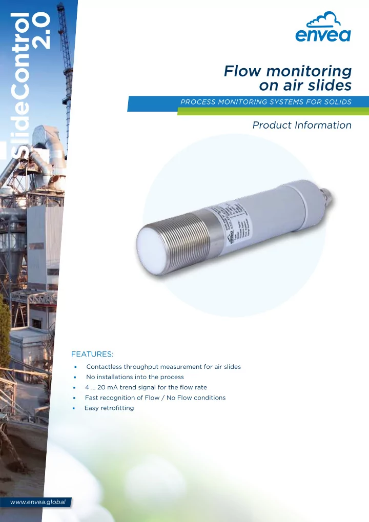
216 30 ø 52 G 1 1/2"

S l i d e C

  • n

t r

  • l

2 .

Sensor Housing material Stainless steel 1.4571 Protection type IP 65 Process temperature

  • 20 … +80 °C
  • 20 … +220 °C (with process adapter)

Ambient temperature

  • 20 … +60 °C

Working pressure

  • Max. 1 bar

Power supply 18 … 24 V DC / AC (powered by transmitter) Measuring frequency 24.125 GHz; ±100 MHz Transmitting power

  • Max. 5 mW

Weight 1.0 kg Dimensions Enclosure: length of 216 mm / diameter of 52 mm Thread: length of 30 mm / diameter of G 1½” Transmitter (DIN Rail) Power supply 24 V DC ± 10 % Power consumption 20 W / 24 VA Protection type IP 40 to EN 60 529 Ambient operating temperature

  • 10 … +45 °C

Dimensions 23 x 90 x 118 mm (W x H x D) Weight

  • Approx. 172 g

DIN rail fastening DIN 60715 TH35 Connection terminals cable cross-section 0.2 - 2.5 mm² [AWG 24-14] Current output 1 x 4 … 20 mA (0 … 20 mA), load < 500 Ω Interface ModBus RTU (RS 485) / USB Pulse output Open Collector - max. 30 V, 20 mA Relay contact

  • Max. rated load: 250 V AC
  • Max. peak current: 6 A
  • Max. rated load 230 V AC: 250 VA
  • Max. breaking capacity DC1:

3/110/220 V: 3/0.35/0.2 A

  • Min. switching load:

500 mW (10 V / 5 mA) Data backup Flash Memory Transmitter (field housing) Power supply 110 / 230 V AC 50 Hz (optional 24 V DC) Power consumption 20 W / 24 VA Protection type IP 65 to EN 60 52910.91 Ambient operating temperature

  • 10 … +45 °C

Dimensions 258 x 237 x 174 mm (W x H x D) Weight

  • Approx. 2.5 kg

Interface RS 485 (ModBus RTU) / USB Cable screw connectors 3 x M20 (4.5 - 13 mm Ø) Connection terminals cable cross-section 0.2 - 2.5 mm² [AWG 24-14] Current output 3 x 4 … 20 mA (0 … 20 mA), load < 500 Ω Pulse output Open Collector - max. 30 V, 20 mA Relay contact

  • Max. rated load: 250 V AC
  • Max. peak current: 6 A
  • Max. rated load 230 V AC: 250 VA
  • Max. breaking capacity DC1:

3/110/220 V: 3/0.35/0.2 A

  • Min. switching load:

500 mW (10 V / 5 mA) Data backup Flash Memory